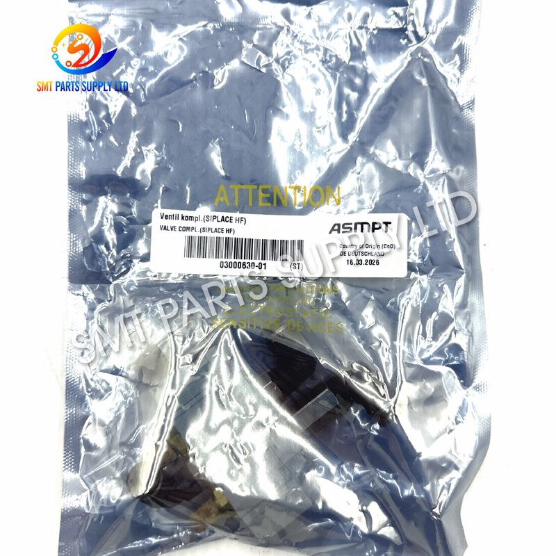
| Brand Name: | ASMPT / SMC |
| Model Number: | SY5120-5LOU-01 |
The ASMPT 03000630-01 SMC SY5120-5LOU-01 solenoid valve assembly is designed for pneumatic directional control in compatible ASMPT and SIPLACE SMT machine configurations. It converts a 24VDC electrical command from the machine-control system into controlled compressed-air switching, allowing the connected pneumatic mechanism to extend, retract, release, clamp, position, or return according to the programmed production sequence.
The SY5120 configuration belongs to the SMC SY5000 family and uses a five-port, two-position, single-solenoid structure. The model code identifies a 24VDC standard coil, an L-type plug connection supplied without the mating connector, integrated indicator and surge-suppression functions, and 1/8-inch A and B working ports.
This valve is suitable for SMT factories, equipment-service companies, machine refurbishers, maintenance departments, and industrial spare-parts distributors. Because externally similar valves can differ in voltage, port size, electrical entry, thread, pilot design, manual override, and accessories, the complete original label should always be checked before ordering.
| Item | Description |
|---|---|
| Product Type | Pneumatic Solenoid Valve Assembly |
| Equipment Part Number | 03000630-01 |
| Valve Model | SY5120-5LOU-01 |
| Common Description | Valve Complete / Valve Compl. |
| Valve Family | SY5000 Series |
| Valve Structure | Five-Port Directional Valve |
| Switching Function | Two-Position Single Solenoid |
| Rated Coil Voltage | 24VDC |
| Electrical Entry | L-Type Plug, Without Mating Connector |
| Indicator Function | Integrated Light |
| Electrical Protection | Surge Voltage Suppressor |
| A and B Port Size | 1/8 Inch |
| Working Medium | Clean, Dry Compressed Air |
| Main Application | SMT Machine Pneumatic Control |
| Recommended Category | SMT Spare Parts / Pneumatic Parts |
| Compatibility Method | Part Number, Label and Interface Verification |
| Benefit | Customer Value |
|---|---|
| Accurate part-number identification | Helps purchasing teams find the required machine spare part efficiently |
| 24VDC control specification | Supports integration with compatible industrial machine-control outputs |
| Two-position single-solenoid design | Provides controlled switching and automatic return behavior |
| Five-port pneumatic structure | Manages supply, actuator and exhaust air paths |
| Compact SY5000 body | Suitable for restricted installation spaces inside SMT machinery |
| Indicator light | Helps technicians identify whether an electrical command is present |
| Surge suppression | Helps protect the electrical switching circuit from coil-generated voltage spikes |
| 1/8-inch working ports | Supports compact pneumatic connections and machine tubing arrangements |
| Maintenance-oriented design | Simplifies inspection, replacement and troubleshooting |
| Export-ready supply | Suitable for international SMT maintenance and spare-parts requirements |
An SMT placement machine depends on stable pneumatic control to complete repeated mechanical actions. Every air-controlled movement must occur at the correct time and reach the required position before the machine continues its programmed sequence.
After extended service, the valve may experience contamination, coil deterioration, connector damage, internal sealing wear, restricted exhaust flow, or unstable spool movement. These conditions can reduce response speed and lead to intermittent machine faults.
| Cause | Possible Result |
|---|---|
| Dust or particles in the compressed air | Internal spool sticking or restricted airflow |
| Excessive water in the air line | Corrosion, unstable switching or seal deterioration |
| Oil mist or carbon contamination | Deposits inside the pilot and main valve passages |
| Incorrect coil voltage | Coil overheating, weak actuation or electrical failure |
| Damaged plug or loose terminal | Intermittent energization |
| Broken lead wire | No response to the machine command |
| Blocked exhaust silencer | Slow actuator movement or incomplete return |
| Crushed pneumatic tubing | Insufficient airflow |
| Air leakage at fittings | Reduced actuator pressure |
| Excessive sealing material | Blocked internal passage |
| Worn internal seals | Continuous leakage or pressure loss |
| Damaged valve body | External air leakage |
| Extended continuous energization | Higher coil temperature and reduced service reliability |
| Incorrect replacement configuration | Wrong switching behavior or installation mismatch |
| Manual override left engaged | Unexpected actuator position or machine alarm |
Official operating guidance recommends clean air preparation, including an upstream air filter with filtration of 5 μm or finer. Excessive drainage should be controlled with suitable drying or water-separation equipment.
| Machine Condition | Possible Valve-Related Cause |
|---|---|
| Pneumatic actuator does not move | Missing voltage, failed coil, low pressure or blocked valve |
| Actuator moves slowly | Restricted supply, leakage, blocked exhaust or contaminated valve |
| Mechanism fails to return | Spool sticking, exhaust restriction or actuator obstruction |
| Machine reports repeated position alarms | Pneumatic movement is incomplete or delayed |
| Operation becomes intermittent | Loose connector, unstable pressure or internal contamination |
| Air leaks continuously | Damaged seal, fitting, tubing or valve body |
| Indicator remains off | No electrical command or wiring fault |
| Indicator illuminates but no motion occurs | Pneumatic or mechanical problem remains |
| Coil becomes unusually hot | Incorrect voltage or abnormal continuous energization |
| Actuator moves in the wrong direction | Tubing connected to incorrect working ports |
A machine alarm does not automatically confirm that the valve is defective. The controller output, connector, cable, air supply, regulator, filter, tubing, sensor, actuator, exhaust silencer, and mechanical assembly should also be inspected.
A structured inspection helps maintenance teams identify the actual fault and avoid unnecessary parts replacement.
| Step | Recommended Action |
|---|---|
| 1 | Record the machine model and serial number |
| 2 | Photograph the installed valve and surrounding components |
| 3 | Record the complete equipment and valve part numbers |
| 4 | Confirm the rated coil voltage |
| 5 | Check whether the machine sends voltage during the command |
| 6 | Inspect the plug, cable and terminals |
| 7 | Confirm adequate compressed-air supply |
| 8 | Check the filter, regulator and moisture level |
| 9 | Inspect tubing for leakage, bending or blockage |
| 10 | Inspect the exhaust ports and silencers |
| 11 | Confirm that the actuator moves freely |
| 12 | Compare the replacement valve with the removed unit |
| 13 | Install the replacement using the original piping arrangement |
| 14 | Restore pressure gradually and inspect for leakage |
| 15 | Test the mechanism in maintenance mode before production |
Two valves can look almost identical while having different operating characteristics.
| Verification Point | Importance |
|---|---|
| Equipment part number | Confirms the machine-specific spare-parts reference |
| Full valve model | Identifies the complete pneumatic and electrical configuration |
| Rated voltage | Prevents coil damage and incorrect operation |
| Valve positions | Determines the available pneumatic switching states |
| Single or double solenoid | Determines return and memory behavior |
| Electrical entry | Must fit the existing wiring and plug arrangement |
| Connector inclusion | The LO configuration does not include the mating connector |
| Indicator and suppressor | Must match the electrical-control requirement |
| Port size | Must fit the installed fittings and required airflow |
| Thread specification | Must match the pneumatic fitting standard |
| Manual override | Must suit the machine-maintenance procedure |
| Pilot configuration | Influences operating-pressure requirements |
| Mounting arrangement | Must match the available machine space |
| Supplied accessories | Determines whether fittings, plug or bracket are included |
| Parameter | Specification |
|---|---|
| Product Name | Complete Pneumatic Solenoid Valve Assembly |
| Equipment Part Number | 03000630-01 |
| Manufacturer Model | SY5120-5LOU-01 |
| Product Series | SY5000 |
| Valve Type | Five-Port Solenoid Valve |
| Body Configuration | Body-Ported Single Unit |
| Switching Type | Two-Position |
| Solenoid Type | Single Solenoid |
| Coil Specification | Standard |
| Rated Voltage | 24VDC |
| Electrical Entry Code | LO |
| Electrical Entry Description | L-Type Plug Connector Without Connector |
| Light and Suppressor Code | U |
| Indicator | With Light |
| Surge Protection | With Non-Polar Surge Voltage Suppressor |
| Working Port Code | 01 |
| A and B Port Size | 1/8 Inch |
| Manual Operation | Manual Override Provided |
| Working Fluid | Compressed Air |
| Installation Function | Directional Pneumatic Control |
| Applicable Equipment | Compatible ASMPT/SIPLACE SMT Machine Configurations |
| Product Category | SMT Machine Pneumatic Spare Part |
| Confirmation Requirement | Verify Complete Label Before Purchase |
The official SY5000 configuration data identifies the series, two-position single actuation, 24VDC voltage, LO electrical entry, U-type light and surge suppressor, and 1/8-inch working-port specification.
| Code | Meaning |
|---|---|
| SY | Pneumatic solenoid valve family |
| 5 | SY5000 series size |
| 1 | Two-position single-solenoid actuation |
| 20 | Body-ported single-valve configuration |
| 5 | 24VDC rated coil |
| LO | L-type plug connector without mating connector |
| U | Light and non-polar surge voltage suppressor |
| 01 | 1/8-inch A and B working ports |
| Operating Item | Recommended Requirement |
|---|---|
| Medium | Clean compressed air |
| Maximum Series Pressure Reference | Up to 0.7 MPa, subject to configuration |
| Ambient and Fluid Temperature | -10°C to 50°C, without freezing |
| Air Filtration | 5 μm or finer recommended upstream |
| Moisture Control | Air dryer or water separator recommended when drainage is excessive |
| Exhaust Condition | Exhaust ports must remain unobstructed |
| Lubrication | Follow the machine and pneumatic-system maintenance standard |
| Installation Environment | Industrial indoor environment |
| Electrical Supply | Stable 24VDC control output |
| Final Confirmation | Refer to the complete installed valve label |
The SY5000 product family is specified for air service, with an ambient and fluid temperature range of -10°C to 50°C without freezing and configurations rated up to 0.7 MPa.
The following comparison helps distinguish common SY5000 actuation families. The full suffix must still be checked because voltage, plug style, suppressor, port, thread and options may differ.
| Model Family | Switching Structure | Solenoid Arrangement | General Operating Behavior | Selection Note |
|---|---|---|---|---|
| SY5120 Series | Two Position | Single Solenoid | Returns to its normal state after de-energization | Referenced actuation family |
| SY5220 Series | Two Position | Double Solenoid | Changes state when the opposite coil is energized | Not a direct substitute |
| SY5320 Series | Three Position | Double Solenoid | Closed-center neutral condition | Requires matching pneumatic circuit |
| SY5420 Series | Three Position | Double Solenoid | Exhaust-center neutral condition | Used for different actuator behavior |
| SY5520 Series | Three Position | Double Solenoid | Pressure-center neutral condition | Must match the original circuit design |
| Entry Code | Connection Type | Purchasing Consideration |
|---|---|---|
| G | Grommet lead-wire type | Fixed wire arrangement |
| H | Extended grommet lead-wire type | Provides additional wire length |
| L | L-type plug with lead wire | Plug orientation must match |
| LN | L-type plug variation | Check supplied connector components |
| LO | L-type plug without mating connector | Existing or separately supplied connector required |
| M | M-type plug with lead wire | Different plug orientation from LO |
| MN | M-type plug variation | Check wiring and connector format |
| MO | M-type plug without connector | Not interchangeable with LO by appearance alone |
| D | DIN terminal with connector | Larger terminal structure |
| DO | DIN terminal without connector | Matching connector required |
| Y | DIN-style terminal configuration | Confirm terminal standard |
| YO | DIN-style terminal without connector | External connector required |
The valve assembly is used for compressed-air directional control in compatible SMT placement-machine systems. It receives an electrical command and controls the air path connected to a pneumatic actuator or machine mechanism.
Depending on the installed pneumatic circuit, the valve may control:
| Pneumatic Function | Typical Purpose |
|---|---|
| Cylinder extension and retraction | Moves a machine mechanism between two positions |
| Clamping and releasing | Holds or releases a component or assembly |
| Positioning movement | Aligns an operating mechanism |
| Locking and unlocking | Controls a pneumatic locking device |
| Lifting and lowering | Raises or lowers a machine section |
| Stopper operation | Controls product or board movement |
| Opening and closing | Operates covers, gates or mechanical elements |
| Air supply switching | Directs compressed air to a selected circuit |
| Exhaust control | Releases air from the opposite actuator chamber |
| Maintenance operation | Supports controlled diagnostic movement |
The precise function of part number 03000630-01 should be confirmed from the machine installation position, pneumatic diagram, service record or removed component.
| Customer Type | Purchasing Purpose |
|---|---|
| Electronics manufacturing factory | Corrective maintenance and emergency repair |
| SMT production department | Critical spare-parts inventory |
| Equipment maintenance company | Customer machine servicing |
| Machine refurbishing company | Pneumatic-system restoration |
| Automation spare-parts distributor | International parts supply |
| Contract electronics manufacturer | Downtime-reduction stock |
| Overseas service engineer | Machine-specific repair work |
| Industrial purchasing department | Part-number-based replacement |
| Requirement | Recommendation |
|---|---|
| Air Quality | Clean, dry and filtered |
| Moisture Level | Minimize condensed water |
| Oil and Carbon Dust | Control with suitable air-treatment equipment |
| Temperature | Maintain within the permitted operating range |
| Freezing | Prevent moisture from freezing |
| Dust | Protect open ports and electrical contacts |
| Chemicals | Avoid aggressive cleaning agents |
| Tubing | Use correctly sized undamaged tubing |
| Exhaust | Keep exhaust passages open |
| Vibration | Secure the valve and electrical plug |
| Maintenance Access | Leave adequate inspection space |
The valve has five principal pneumatic paths.
| Port Identification | General Function |
|---|---|
| P or 1 | Main compressed-air supply |
| A or 4 | Working connection to one side of an actuator |
| B or 2 | Working connection to the opposite actuator side |
| EA or 5 | Exhaust path for one working circuit |
| EB or 3 | Exhaust path for the other working circuit |
When the coil is not energized, the valve remains in its normal position. The internal spool connects the pressure-supply port to one actuator port while the opposite actuator port is connected to exhaust.
The connected pneumatic mechanism therefore remains in or returns toward its normal machine position.
When the controller supplies 24VDC:
When the electrical command is removed:
The indicator light helps maintenance personnel check whether the solenoid is receiving an electrical command.
The surge suppressor helps reduce the voltage spike generated when the coil is switched off. The U configuration is identified as a light-equipped, non-polar surge-suppression type.
An illuminated indicator does not guarantee that air is switching correctly. Insufficient air pressure, internal contamination, blocked exhaust, damaged tubing or mechanical obstruction may still prevent actuator movement.
Before removing the original valve:
| Stage | Action |
|---|---|
| Identification | Compare the old and new part numbers |
| Electrical Check | Confirm 24VDC and LO plug configuration |
| Pneumatic Check | Confirm port size and tubing positions |
| Mechanical Check | Confirm mounting clearance |
| Removal | Disconnect plug and tubes carefully |
| Cleaning | Clean the surrounding area without introducing debris |
| Fitting Installation | Install compatible fittings with controlled sealing material |
| Valve Mounting | Secure the valve without excessive force |
| Tube Connection | Reconnect according to the original port positions |
| Electrical Connection | Install the correct mating plug |
| Pressure Restoration | Restore air gradually |
| Leakage Test | Inspect every connection |
| Functional Test | Operate in maintenance mode |
| Production Check | Confirm normal response before full operation |
Operating the manual override can immediately actuate connected equipment. Personnel should confirm that the movement is safe before using it. After valve replacement, stored compressed air must be controlled and measures should be taken to prevent sudden actuator movement.
Do not:
| Problem | Possible Cause | Recommended Check |
|---|---|---|
| Valve does not energize | No 24VDC command | Measure the control voltage |
| Indicator does not illuminate | Wiring or output failure | Inspect plug, cable and controller |
| Indicator illuminates without movement | Pneumatic or mechanical fault | Check pressure, spool and actuator |
| Actuator moves slowly | Restricted supply or exhaust | Inspect regulator, tubing and silencer |
| Actuator moves incorrectly | Tubing reversed | Compare piping with original records |
| Valve leaks continuously | Seal, fitting or body damage | Locate the exact leakage point |
| Coil becomes hot | Incorrect voltage or continuous duty | Stop and verify electrical conditions |
| Valve works intermittently | Loose plug or contaminated air | Check connector and air preparation |
| Mechanism does not return | Blocked exhaust or mechanical obstruction | Test valve and actuator separately |
| Alarm remains after replacement | Fault is elsewhere in the system | Inspect sensors, output and mechanism |
Official guidance notes that long continuous energization can increase coil temperature and may affect the valve or nearby equipment. Suitable heat management should be considered where extended energization is unavoidable.
| Selection Item | Required Information |
|---|---|
| Machine Manufacturer | ASMPT/SIPLACE or corresponding equipment identification |
| Machine Model | Exact installed machine model |
| Machine Serial Number | Recommended for configuration verification |
| Equipment Part Number | 03000630-01 |
| Valve Model | SY5120-5LOU-01 |
| Rated Voltage | 24VDC |
| Valve Structure | Five Port |
| Actuation | Two-Position Single Solenoid |
| Electrical Entry | LO |
| Connector | Confirm existing or separately required plug |
| Indicator and Suppressor | U configuration |
| Working Port Size | 1/8 Inch |
| Thread Standard | Confirm from complete label and fittings |
| Pilot Design | Confirm original configuration |
| Tubing Direction | Compare all original connections |
| Mounting Position | Compare available clearance |
| Accessories | Confirm fittings, connector and bracket requirements |
| Product Condition | Confirm required supply condition |
| Quantity | State the required purchasing quantity |
| Destination | Provide country or delivery location |
Please provide:
A valve should not be selected only because:
A small suffix difference can change voltage, plug type, suppressor, thread, pilot design or operating behavior.
Before shipment, the following checks can be performed according to the quoted condition and agreed order requirements.
| Inspection Item | Inspection Purpose |
|---|---|
| Equipment part-number check | Confirms the requested machine reference |
| Valve-label check | Confirms the complete model |
| Appearance inspection | Identifies visible damage or contamination |
| Port inspection | Checks openings and threads |
| Coil inspection | Checks visible coil condition |
| Plug-entry inspection | Confirms LO connection style |
| Manual-override inspection | Checks visible operating condition |
| Accessory inspection | Confirms quoted components |
| Quantity verification | Prevents packing discrepancies |
| Packaging inspection | Reduces transport damage |
Functional testing requirements should be agreed before order confirmation because the necessary fixtures and testing procedures may vary.
| Packaging Method | Purpose |
|---|---|
| Clean protective bag | Prevents dust contamination |
| Port protection | Prevents debris entering pneumatic passages |
| Anti-impact wrapping | Protects the body and coil |
| Individual inner box | Separates each valve |
| Reinforced export carton | Supports international transportation |
| Identification label | Displays the model and quantity |
| Moisture protection | Supports storage and long-distance transport |
No. Compatibility depends on the machine configuration and installed pneumatic circuit. Please confirm the machine model, complete original label, part number, voltage, plug, port arrangement, fittings and mounting position before ordering.
The model code identifies a 24VDC standard coil. The machine output should still be measured and confirmed before installation to prevent incorrect operation or electrical damage.
The LO code identifies an L-type plug entry without the mating connector. Confirm whether the order requires the valve only, a separate connector, lead wires, fittings or a complete machine-specific assembly.
Not automatically. Other SY5000 models may have different actuation, voltage, connector, port, thread, pilot or neutral-position characteristics. The complete model and machine-control requirements must match.
Please provide the required quantity, equipment part number, complete valve model, machine model, clear label photographs, connector photograph, installation photograph, requested condition, delivery country and expected delivery date.
Contact our sales team for availability, compatibility confirmation, lead time, pricing, packaging and international shipping information.
To receive a fast and accurate quotation, please include:
We welcome inquiries from SMT factories, equipment-maintenance companies, machine refurbishers, industrial distributors and electronics manufacturers in Europe, North America, Southeast Asia and other international markets.
Trademark Notice: Brand names and model references are used only for product identification and compatibility confirmation. All trademarks remain the property of their respective owners.