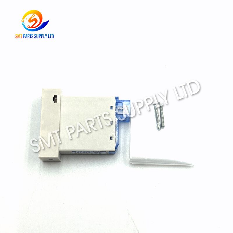
| Brand Name: | KOGANEI |
| Model Number: | KHY-M7153-101 |
YAMAHA KHY-M7153-101 KOGANEI JA10AA-36W YS24 SMT Solenoid Valve
![]()
![]()
![]()
The YAMAHA KHY-M7153-101 KOGANEI JA10AA-36W is a compact pneumatic solenoid valve designed for air-circuit switching within an SMT pick-and-place machine head or related pneumatic assembly. The exact KHY-M7153-101 part number is primarily associated with YS24 equipment, while closely related KHY-M7153-10 and KHY-M7153-10X references are also found in valve applications for YG12, YS12, YS24, YG12F, and YS12F machines. Exact compatibility should always be confirmed from the installed valve label, machine revision, manifold arrangement, and connector configuration.
Installed in a high-speed placement machine, the valve helps switch pneumatic airflow required for vacuum generation, vacuum release, blowing, or other placement-head operations. Its compact body is suitable for limited installation space, while the rapid electrical-to-pneumatic response supports repetitive component pickup and placement cycles. It is suitable for preventive maintenance, head-unit repair, pneumatic troubleshooting, and replacement of a damaged or slow-switching valve.
Product Identification
| Item | Information |
|---|---|
| Product name | SMT Pneumatic Solenoid Valve |
| Machine part number | KHY-M7153-101 |
| Valve model | KOGANEI JA10AA-36W |
| Valve series | JA Series |
| Primary application | YS24 SMT pick-and-place machine |
| Related part references | KHY-M7153-10, KHY-M7153-10X |
| Main function | Pneumatic air and vacuum circuit switching |
| Installation area | Placement head, ejector assembly, pneumatic manifold, or related head mechanism |
| Product category | SMT Machine Parts |
| Unit of supply | One piece |
| Supply condition | Original new or other supply grade according to quotation |
| Compatibility requirement | Confirm part number, valve marking, connector, voltage, and manifold position |
Cause
An SMT solenoid valve operates repeatedly during component pickup, transportation, alignment, placement, and release. Because it performs a large number of switching cycles, valve performance may gradually decline due to internal wear, contamination, electrical failure, or leakage elsewhere in the pneumatic circuit.
A machine alarm does not always mean that the valve itself has failed. The air filter, vacuum generator, tubing, nozzle, manifold seal, connector, wiring, and control signal should also be inspected before replacement.
Common Problems and Possible Causes
| Machine symptom | Possible valve-related cause | Other items to inspect |
|---|---|---|
| Unstable component pickup | Slow valve switching or internal leakage | Nozzle, vacuum filter, hose, ejector, pickup height |
| Low vacuum level | Valve does not open completely | Air pressure, vacuum generator, manifold seal, blocked tubing |
| Component drops during movement | Intermittent air control or delayed response | Nozzle wear, component settings, head cable, vacuum sensor |
| Poor component release | Exhaust or blow circuit does not switch correctly | Blow pressure, exhaust path, nozzle contamination |
| Repeated pickup error | Valve response becomes inconsistent after heating | Coil, connector, machine output signal, air quality |
| No pneumatic action | Coil does not receive or respond to the control signal | Harness, driver output, connector pins, machine fuse |
| Continuous air leakage | Internal valve seal or manifold gasket may be damaged | Tube fittings, sub-base seal, adjacent valves |
| Valve operates manually but not automatically | Electrical control or wiring problem | Machine output board, cable continuity, connector polarity |
| New valve cannot be installed | Incorrect valve revision or manifold arrangement | Old part number, mounting holes, port direction, connector type |
| Valve becomes noisy | Unstable air supply or internal contamination | Regulator, air dryer, filter element, mounting screws |
Why Valve Performance May Decline
| Cause | Effect on operation |
|---|---|
| Moisture in compressed air | May cause corrosion, sticking, or irregular movement |
| Dust or oil contamination | Can restrict internal passages and affect sealing |
| Long-term high-cycle use | Gradually wears seals and moving parts |
| Incorrect operating pressure | Can produce weak, delayed, or unstable switching |
| Damaged connector pins | Causes intermittent electrical contact |
| Incorrect coil voltage | May prevent operation or damage the coil |
| Loose manifold screws | Produces external leakage and unstable airflow |
| Damaged gasket or O-ring | Allows pressure or vacuum loss between valve and manifold |
| Wrong valve code | May create different port logic or electrical characteristics |
| Incorrect installation direction | Can connect supply, output, and exhaust paths incorrectly |
Solution
Replacing a malfunctioning KHY-M7153-101 valve with a correctly matched JA10AA-36W unit can help restore the intended pneumatic switching function of the placement-head air circuit.
A properly selected replacement may help improve vacuum response, component pickup stability, release timing, and machine operating consistency. However, replacement should be completed only after checking the complete pneumatic and electrical circuit.
Recommended Troubleshooting and Replacement Process
| Step | Action | Purpose |
|---|---|---|
| 1 | Record the machine model and serial number | Identifies the correct machine generation |
| 2 | Read the complete old valve marking | Confirms JA10AA-36W and any suffix information |
| 3 | Confirm machine part number KHY-M7153-101 | Prevents confusion with KHY-M7153-00 or KHY-M7153-01 versions |
| 4 | Photograph the connector and manifold | Confirms wiring direction and mounting configuration |
| 5 | Check air pressure and air quality | Rules out supply-side problems |
| 6 | Inspect tubing, nozzle, filter, and ejector | Finds leakage or blockage outside the valve |
| 7 | Test the machine output signal | Confirms that the valve receives the correct control voltage |
| 8 | Compare the replacement physically | Checks dimensions, ports, screws, seals, and connector |
| 9 | Install with the correct gasket | Prevents manifold leakage |
| 10 | Run pickup and release tests | Confirms stable operation before production resumes |
Operational Benefits
| Benefit | Practical value |
|---|---|
| Compact installation | Suitable for restricted space inside SMT head assemblies |
| Fast pneumatic control | Supports repetitive pickup and placement operations |
| Stable airflow switching | Helps maintain consistent vacuum and blow functions |
| Machine-specific identification | KHY-M7153-101 simplifies maintenance-part matching |
| Replaceable construction | Reduces the need to replace a larger pneumatic assembly |
| Maintenance support | Useful for scheduled service and emergency machine repair |
| Clear valve marking | JA10AA-36W assists visual verification before ordering |
| Individual supply | Convenient for keeping critical replacement stock |
Specifications
Machine-Specific Product Specifications
| Specification | Details |
|---|---|
| Brand reference | YAMAHA |
| Pneumatic component manufacturer | KOGANEI |
| Machine part number | KHY-M7153-101 |
| Pneumatic valve model | JA10AA-36W |
| Component type | Internal pneumatic solenoid valve |
| Primary machine application | YS24 SMT pick-and-place machine |
| Related machine family | YG12, YS12, YS24, YG12F, and YS12F subject to part-number verification |
| Main operating medium | Compressed air |
| Main machine function | Switching air, vacuum-generation, exhaust, or blow circuits |
| Installation method | Manifold or machine-specific sub-base mounting |
| Electrical connection | Machine-specific connector or lead arrangement |
| Port configuration | Confirm against the removed valve |
| Rated voltage | Confirm from the original valve label and machine circuit |
| Operating pressure | Follow the machine specification and exact valve label |
| Lubrication | Follow equipment manufacturer maintenance requirements |
| Package | Protective individual packaging |
| Minimum order quantity | One piece |
| Inspection before shipment | Part-number and visual-condition inspection |
| Warranty | According to the confirmed supply condition and quotation |
KOGANEI JA-Series Reference Data
KOGANEI describes the JA Series as a thin, compact solenoid-valve platform with an approximately 10.5 mm valve width. The series supports several pneumatic configurations, including two-port, three-port, five-port, and tandem three-port arrangements. The exact specification of JA10AA-36W must still be confirmed from the installed product because machine-specific suffixes can represent customized electrical or mounting requirements.
| JA-Series Reference Item | Catalog-Level Reference |
|---|---|
| Operating medium | Air |
| Operation principle | Internal pilot type |
| Series operating pressure | Approximately 0.2–0.7 MPa |
| Series proof pressure | Approximately 1.05 MPa |
| Series operating temperature | Approximately 5–50°C |
| Lubrication | Generally not required for the catalog series |
| Mounting direction | Series catalog permits flexible mounting |
| Standard catalog voltage | DC24V |
| Standard catalog voltage range | DC21.6–26.4V |
| Standard catalog power consumption | Approximately 0.5W |
| Low-current holding consumption | Approximately 0.25W |
| Valve width | Approximately 10.5 mm |
| Available series port arrangements | Two-port, three-port, five-port, and tandem three-port |
| Typical fitting references | φ4, φ6, or Rc1/8 depending on configuration |
| Main body material reference | Anodized aluminum alloy |
| Seal material reference | Synthetic rubber |
The values above are JA-Series catalog references rather than a guarantee for every customized JA10AA-36W machine valve. Final selection must be based on the complete old-valve marking and machine configuration. Official JA-Series catalog information lists air as the medium, internal-pilot operation, a 0.2–0.7 MPa operating-pressure range, DC24V standard voltage, and multiple port configurations.
Important Model-Code Notice
The “36W” characters in JA10AA-36W should be treated as part of the complete valve model designation. They should not automatically be interpreted as a 36-watt electrical power rating.
Before installation, confirm:
| Confirmation item | Required information |
|---|---|
| Complete valve marking | JA10AA-36W |
| Machine part number | KHY-M7153-101 |
| Coil voltage | Read from the original valve or machine electrical drawing |
| Connector shape | Must match the existing harness |
| Cable direction | Must fit the original installation space |
| Port arrangement | Must align with the original manifold |
| Manual override position | Must match service-access requirements |
| Valve station | Confirm the exact location in the head manifold |
| Gasket pattern | Must match all manifold ports |
| Machine revision | Confirm using machine serial number |
Application
The KHY-M7153-101 JA10AA-36W solenoid valve is used in an SMT machine pneumatic system where an electrical control signal must quickly switch compressed air between different pneumatic paths.
Primary Application Areas
| Application | Valve function |
|---|---|
| SMT placement head | Controls pneumatic action required during pickup or release |
| Vacuum-generation circuit | Directs air to or from the vacuum ejector system |
| Vacuum release circuit | Assists rapid release of the placed component |
| Blow-air circuit | Controls positive air used during nozzle or component release |
| Head pneumatic manifold | Operates as one valve station within a compact valve group |
| Machine maintenance | Replaces a leaking, damaged, slow, or electrically failed valve |
| Preventive spare-parts stock | Reduces downtime when a critical valve fails |
| Head-unit refurbishment | Restores pneumatic functions during head overhaul |
Machine Compatibility Guide
| Machine model | Compatibility status |
|---|---|
| YS24 | Primary application associated with KHY-M7153-101 |
| YS12 | Related KHY-M7153-10 or KHY-M7153-10X valve family; verify exact part |
| YG12 | Related valve-family application; verify exact part and manifold |
| YG12F | Related valve-family application; confirmation required |
| YS12F | Related valve-family application; confirmation required |
| Other machines | Do not order only by appearance; provide the old valve details |
The exact KHY-M7153-101 reference has been listed specifically as a YS24 valve, while JA10AA-36W valves carrying KHY-M7153-10 or KHY-M7153-10X references are also marketed for several YG and YS machine models. The safest ordering method is to match the complete part number and old-valve photograph instead of relying only on the machine family.
Suitable Buyers
| Buyer type | Typical requirement |
|---|---|
| SMT production factory | Emergency replacement for a stopped machine |
| EMS manufacturer | Preventive spare-parts inventory |
| SMT maintenance company | Repair and refurbishment of head assemblies |
| Used-equipment dealer | Machine preparation before resale |
| SMT parts distributor | Stock for recurring customer demand |
| Technical service team | Pneumatic-system troubleshooting |
| Overseas importer | Consolidated SMT spare-parts purchasing |
![]()
![]()
![]()
How It Works
A solenoid valve converts an electrical control command into pneumatic switching. Within an SMT placement machine, the controller sends a voltage signal when a vacuum, release, blow, or other air operation is required.
Operating Sequence
| Stage | Valve action | Machine result |
|---|---|---|
| 1. Standby | Valve remains in its default pneumatic position | Air circuit waits for the next machine command |
| 2. Electrical signal | The machine sends voltage to the solenoid coil | A magnetic field is generated |
| 3. Internal movement | The plunger and pilot mechanism move | The main internal passage changes position |
| 4. Air switching | Supply, output, or exhaust paths are connected | Air reaches the required head circuit |
| 5. Vacuum or blow action | The ejector or pneumatic output responds | The nozzle picks up or releases the component |
| 6. Signal removal | Coil power is removed or switched | The valve returns or changes to the commanded state |
| 7. Repeated cycle | The process repeats during production | Components are handled continuously |
The JA Series includes different port and position arrangements. Therefore, the internal airflow logic of the replacement valve must match the original unit. A valve with a similar external size but a different internal function may not operate the machine correctly.
Relationship With the SMT Head System
| Related component | Relationship with the valve |
|---|---|
| Nozzle | Receives the vacuum or release effect controlled by the pneumatic circuit |
| Vacuum ejector | Generates vacuum when supplied with compressed air |
| Vacuum sensor | Detects whether sufficient pickup vacuum has been achieved |
| Air tubing | Transfers pressure or vacuum between components |
| Filter | Helps prevent contaminants from entering the valve and ejector |
| Manifold | Distributes compressed air among several valves |
| Head control board | Sends the electrical switching command |
| Harness and connector | Carries voltage from the control circuit to the coil |
How To Choose
Correct valve selection is essential because different KHY-M7153 versions may have similar bodies but different machine applications, coil specifications, connectors, or pneumatic functions.
Selection Checklist
| Selection point | What to confirm | Why it matters |
|---|---|---|
| Machine part number | KHY-M7153-101 | Most important identification for machine maintenance |
| Valve model | JA10AA-36W | Confirms the pneumatic component marking |
| Machine model | YS24 or another related model | Prevents installation in an unsupported machine |
| Machine serial number | Complete serial number | Helps identify machine generation and revision |
| Old valve photograph | Front, rear, top, connector, and label | Allows physical comparison |
| Connector | Shape, pin count, key direction | Prevents electrical mismatch |
| Coil voltage | Original label or circuit drawing | Protects the coil and control output |
| Manifold position | Exact valve station | Confirms the function and port arrangement |
| Gasket pattern | Number and position of air passages | Prevents leakage or blocked ports |
| Screw position | Mounting-hole spacing and screw length | Ensures secure installation |
| Cable direction | Left, right, top, or bottom | Avoids interference inside the head |
| Supply condition | Original new, used, or compatible | Determines price, warranty, and expected service life |
| Required quantity | Maintenance quantity and safety stock | Supports production planning |
| Delivery deadline | Standard or urgent shipment | Allows suitable logistics arrangement |
Do Not Select Only by Appearance
Two valves may look almost identical but have different:
| Possible difference | Risk of incorrect selection |
|---|---|
| Coil voltage | Valve may not operate or may be damaged |
| Internal pneumatic logic | Vacuum and exhaust functions may be reversed |
| Connector pin assignment | Machine signal may not reach the correct coil |
| Manifold port pattern | Air leakage or blocked airflow may occur |
| Cable orientation | Valve may not fit in the available space |
| Manual override design | Service access may be restricted |
| Part-number revision | Machine software or head configuration may differ |
| Seal thickness | Manifold leakage may occur after installation |
Information Required for an Accurate Quotation
Please provide the following information when sending an inquiry:
| Required information | Example |
|---|---|
| Machine model | YS24 |
| Machine serial number | Full number from machine nameplate |
| Machine part number | KHY-M7153-101 |
| Valve model | KOGANEI JA10AA-36W |
| Required quantity | 1, 2, 5, or more pieces |
| Required condition | Original new or other requested grade |
| Destination country | Country and postal code |
| Old valve photographs | Clear label and connector images |
| Fault description | Low vacuum, leakage, no switching, or intermittent response |
| Delivery requirement | Standard shipment or urgent replacement |
Installation Guidance
Installation should be performed by qualified maintenance personnel after the equipment is stopped, isolated, and depressurized.
Installation Procedure
| Step | Instruction |
|---|---|
| 1 | Stop the machine according to the approved maintenance procedure |
| 2 | Disconnect electrical power and compressed-air supply |
| 3 | Release residual pressure from the pneumatic system |
| 4 | Record the old valve position, connector direction, and tubing arrangement |
| 5 | Remove the electrical connector without pulling the cable |
| 6 | Remove the valve mounting screws evenly |
| 7 | Inspect the manifold surface, gasket, and air passages |
| 8 | Compare the old and new valves before installation |
| 9 | Install the correct gasket in the correct orientation |
| 10 | Tighten mounting screws evenly without excessive force |
| 11 | Reconnect the harness and confirm secure engagement |
| 12 | Restore air pressure and check for leakage |
| 13 | Restore machine power and perform a manual-output test |
| 14 | Run pickup, transfer, and release tests at reduced speed |
| 15 | Confirm stable operation before returning to normal production |
Maintenance Recommendations
| Maintenance item | Recommended action |
|---|---|
| Compressed-air filter | Inspect and replace according to factory maintenance intervals |
| Air dryer | Confirm correct operation and drain moisture |
| Tubing | Inspect for cracks, kinks, loose fittings, or contamination |
| Manifold gasket | Replace when hardened, damaged, or deformed |
| Electrical connector | Keep clean, fully inserted, and free from loose pins |
| Valve exterior | Keep free from flux, oil, dust, and cleaning-liquid residue |
| Vacuum filter | Clean or replace before assuming the valve has failed |
| Nozzle condition | Check wear, blockage, and sealing surface |
| Spare inventory | Keep at least one confirmed valve for critical production machines |
| Maintenance records | Record replacement date, machine number, and failure symptom |
Quality and Order Confirmation
To reduce incorrect orders, the valve should be checked using both machine and pneumatic-component identification.
Pre-Shipment Confirmation
| Inspection point | Confirmation method |
|---|---|
| Part number | Compare with purchase order |
| Valve model | Check JA10AA-36W label |
| External condition | Visual inspection |
| Connector condition | Check pins, housing, and cable |
| Mounting surface | Check for visible damage |
| Packaging | Individual protective packaging |
| Quantity | Count before dispatch |
| Customer compatibility information | Compare with supplied machine and old-part details |
Recommended Spare-Parts Strategy
For factories using several machines of the same model, maintaining a small quantity of confirmed valves can reduce waiting time during an unexpected pneumatic failure. The recommended stock quantity should be based on machine count, production hours, historical failure frequency, supplier lead time, and the importance of the production line.
FAQ
1. Is KHY-M7153-101 the same as KHY-M7153-10 or KHY-M7153-10X?
These references belong to a closely related valve family, but they should not automatically be treated as completely interchangeable. Confirm the full valve marking, machine model, connector, manifold position, coil specification, and pneumatic port arrangement. A photograph of the installed valve is strongly recommended before ordering.
2. Which SMT machine uses the KHY-M7153-101 JA10AA-36W valve?
KHY-M7153-101 is primarily associated with the YS24 SMT pick-and-place machine. Related KHY-M7153-10 and KHY-M7153-10X JA10AA-36W references may also appear in YG12, YS12, YS24, YG12F, and YS12F applications, but exact compatibility must be confirmed.
3. Does “36W” mean that the valve consumes 36 watts?
No conclusion about electrical power consumption should be made from the “36W” suffix alone. It is part of the complete JA10AA-36W model designation. Confirm the actual rated voltage and electrical specification from the original valve label, machine drawing, or approved technical documentation before installation.
4. Can this valve solve low-vacuum or pickup-error problems?
It may solve the problem when the original valve has internal leakage, slow switching, contamination, coil failure, or unstable operation. However, low vacuum can also be caused by a blocked nozzle, worn filter, damaged tubing, leaking gasket, weak ejector, incorrect pickup height, or sensor problem.
5. What information should be provided before receiving a quotation?
Please send the machine model, serial number, KHY-M7153-101 part number, JA10AA-36W valve marking, required quantity, preferred supply condition, destination country, and clear photographs of the old valve label, connector, cable direction, manifold surface, and installation position.
Contact Us
For pricing, availability, compatibility confirmation, and international delivery, please send your machine information and old valve photographs with your inquiry.
For faster confirmation, include:
Machine Model + Machine Serial Number + Part Number + Valve Model + Quantity + Delivery Country