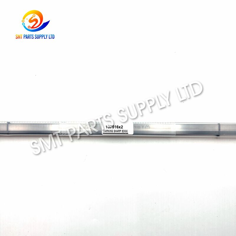
The DEK 137516 board clamp foil is a precision printer spare part used to support and secure printed circuit boards during the solder paste printing process. It is commonly cross-referenced with part numbers 215607 and 03128529 and is supplied for compatible DEK screen printer configurations requiring a 500mm foil or shim board clamp assembly.
During printing, the PCB must remain flat, correctly positioned and stable beneath the stencil. A worn, bent or incorrectly fitted board clamp foil can allow the PCB edge to move or lift, resulting in solder paste misalignment, uneven deposit height, incomplete pad coverage or excessive paste leakage. Replacing the damaged clamp foil helps restore reliable PCB support and more consistent printing performance.
This component is suitable for SMT factories, electronics manufacturing service providers, printer maintenance companies and spare-parts distributors. Compatibility should be confirmed according to the original part number, installed clamp structure, machine model, rail configuration and actual foil length before ordering.
| Item | Description |
|---|---|
| Brand Reference | DEK |
| Main Part Number | 137516 |
| Cross-Reference Number | 215607 |
| Additional Reference | 03128529 |
| Product Name | Board Clamp Foil Assembly |
| Alternative Name | Foil Shim Board Clamp |
| Nominal Length | 500mm |
| Product Category | SMT Solder Paste Printer Spare Part |
| Installation Position | PCB Transport and Clamping Area |
| Typical Supply Form | Pair or matched set |
| Application | PCB edge support during stencil printing |
| Compatible Equipment | Compatible DEK 02i, 03i and selected Horizon configurations |
| Verification Requirement | Confirm part number, length and clamp configuration |
The board clamp foil operates close to the PCB transport rail and repeatedly contacts or supports PCB edges. Continuous production cycles, mechanical pressure, improper adjustment and contamination can gradually affect its shape and performance.
| Cause | Possible Effect |
| Long-term mechanical cycling | Foil fatigue, deformation or reduced support |
| Incorrect rail adjustment | Uneven loading or excessive pressure |
| PCB collision | Bent or damaged foil edge |
| Excessive clamp force | Distortion or premature wear |
| Solder paste contamination | Restricted movement or unstable support |
| Incorrect installation | Uneven PCB height or poor alignment |
| Wrong foil length | Interference with transport or clamping movement |
| Improper cleaning tools | Scratches, burrs or surface damage |
| Repeated handling | Accidental bending during maintenance |
| Damaged related clamp parts | Abnormal pressure transferred to the foil |
A small deformation may appear insignificant during visual inspection, but it can affect PCB seating and print repeatability. High-density PCB assemblies, fine-pitch components and narrow stencil apertures are especially sensitive to unstable board support.
Production and maintenance teams should inspect the clamp assembly when one or more of the following conditions occur:
These symptoms may also involve other printer components. The transport rails, board stops, support tooling, sensors, cylinders and clamp actuators should therefore be inspected together when diagnosing printing instability.
Replacing the damaged board clamp foil with the correctly matched 500mm assembly can help restore the original clamping geometry and improve PCB stability during stencil printing.
The DEK 137516 / 215607 board clamp foil is designed to provide a controlled supporting surface along the PCB edge. When correctly installed and adjusted, it helps keep the circuit board in a repeatable position while the stencil contacts the PCB and the squeegee moves across the printing area.
| Benefit | Production Value |
| Stable PCB positioning | Helps reduce movement during printing |
| Consistent edge support | Supports more uniform stencil contact |
| Improved print repeatability | Helps maintain stable paste deposits |
| Reduced alignment variation | Supports accurate board positioning |
| Smooth transport transition | Helps prevent interference at the rail area |
| Reliable clamping action | Restores normal mechanical operation |
| Lower defect risk | Helps reduce printing-related rework |
| Fast maintenance replacement | Minimizes unnecessary machine downtime |
| Cross-reference availability | Simplifies spare-part identification |
| Suitable for preventive maintenance | Supports planned printer servicing |
The clamp foil should not be considered an independent correction for every solder paste printing defect. Proper stencil condition, squeegee pressure, board support, printer calibration, rail width and PCB warpage must also be controlled.
| Specification | Details |
| Product Type | Board clamp foil assembly |
| Main Part Number | 137516 |
| Reference Part Number | 215607 |
| Additional Part Number | 03128529 |
| Nominal Length | 500mm |
| Functional Type | Foil or shim-style PCB clamp |
| Application Equipment | SMT solder paste screen printer |
| Installation Area | PCB transport rail and board clamp section |
| Primary Function | Supporting and securing PCB edges |
| Supply Configuration | Normally supplied as a pair or matched set |
| Condition Options | New original or compatible type, subject to quotation |
| Material Description | Precision metallic foil/shim structure |
| Exact Material Grade | Confirm according to ordered specification |
| Surface Requirement | Smooth working edge without harmful burrs |
| Dimensional Check | Recommended before installation |
| Packaging | Protective individual packaging |
| Inspection | Appearance and dimensional verification before shipment |
| Service Type | Replacement and preventive-maintenance spare part |
| Compatibility | Machine configuration must be confirmed |
| Order Method | By part number, machine model and product photographs |
The 500mm designation refers to the nominal clamp foil length. It should not automatically be interpreted as the maximum printable PCB width or total machine rail width. Actual machine capability depends on the printer model, transport system, installed rail configuration and production setup.
| Reference | Description |
| 137516 | Commonly used DEK clamp foil reference |
| 215607 | Cross-reference for the 500mm board clamp foil assembly |
| 03128529 | Additional assembly reference used in the market |
| 03128529-01 | Related reference that may appear in some inventories |
| 500mm | Nominal foil assembly length |
| Foil Shim | Common alternative product description |
| Board Clamp Blade | Alternative market description |
| Board Clamp Foil | Standard product description used by suppliers |
Part-number references can differ according to machine generation, supplier database, revision or historical numbering system. Customers should provide photographs of the installed part and machine nameplate when there is any uncertainty.
The 137516 board clamp foil is used in the PCB handling and clamping system of compatible DEK solder paste printers.
| Industry | Example Products |
| Automotive Electronics | Control modules, sensors and lighting boards |
| Consumer Electronics | Control boards and compact electronic assemblies |
| Industrial Controls | PLC boards, power-control boards and interfaces |
| Communication Equipment | Network, telecom and signal-processing boards |
| Medical Electronics | Monitoring and diagnostic equipment PCBs |
| LED Manufacturing | Lighting drivers and LED control boards |
| Power Electronics | Power supplies, converters and control assemblies |
| Home Appliances | Controller boards and interface modules |
| Aerospace Supply Chain | Specialized low-volume electronic assemblies |
| EMS Manufacturing | Multi-customer PCB assembly production |
The board clamp foil works as part of the printer’s PCB transport and support system.
During this sequence, the clamp foil must remain straight and correctly aligned. Its working edge should support the board without creating excessive pressure, scratching the PCB or interfering with conveyor movement.
A correctly functioning foil helps maintain the PCB at a stable height relative to the stencil. This is particularly important when printing boards with fine-pitch pads, small passive component footprints, bottom-terminated components or edge-located apertures.
Solder paste printing depends on several controlled relationships:
When the clamp foil is bent, the PCB may sit at an incorrect height near one edge. This can produce an uneven stencil-to-board gap or cause the PCB to shift during squeegee movement.
| Problem | Possible Clamp-Related Cause |
| Paste offset | PCB movement during printing |
| Uneven deposit height | Inconsistent stencil contact |
| Insufficient paste | PCB edge positioned too low |
| Paste smearing | Board movement during separation |
| Bridging | Misalignment or unstable support |
| Incomplete apertures | Uneven board-to-stencil contact |
| Edge-area defects | Poor PCB edge support |
| Repeated registration errors | Clamp deformation or incorrect setup |
| Board scratches | Burrs or damaged foil surface |
| Conveyor interruption | Incorrect foil installation or length |
Because multiple printing parameters may create similar defects, maintenance staff should verify the entire clamping and support system before deciding on corrective action.
Choosing only by visual appearance can result in incorrect installation. Several DEK clamp foils may look similar but differ in length, mounting arrangement, revision or application.
| Verification Item | Information Required |
| Original part number | 137516, 215607, 03128529 or another number |
| Nominal length | Confirm that 500mm is required |
| Machine model | DEK 02i, 03i, Horizon or other model |
| Machine serial number | Recommended for configuration checking |
| Installed rail type | Standard, quick-fit or special configuration |
| Supply quantity | One piece, pair or complete assembly |
| Original-part photograph | Front, back and mounting-point images |
| Mounting pattern | Hole positions and fixing structure |
| Existing foil dimensions | Length, width and mounting distance |
| Required condition | Original new or compatible new |
| Production requirement | Standard replacement or urgent breakdown |
| Related damaged parts | Clamp body, rail, cylinder or fastener |
For a faster and more accurate quotation, send:
Providing these details reduces the risk of supplying a visually similar but mechanically incompatible part.
Different printer and rail configurations may use different foil lengths.
| Clamp Type | Typical Identification | |
| 250mm Clamp Foil | Commonly associated with shorter clamp configurations | |
| 340mm Clamp Foil | Used on certain medium-length rail arrangements | |
| 380mm Clamp Foil | Used on specific machine configurations | |
| 500mm Clamp Foil | Associated with 137516 / 215607 / 03128529 | |
| 520mm Foil or Shim | May refer to another quick-fit clamp configuration |
Do not replace a 500mm foil with a 520mm foil simply because the dimensions appear close. Differences in mounting position, profile and mechanical travel can affect machine operation.
Depending on stock, budget and maintenance requirements, different sourcing options may be available.
| Supply Option | Recommended Application |
| Original New | Customers requiring original manufacturer supply |
| Compatible New | Cost-controlled maintenance and production replacement |
| Sample-Based Production | Older or uncommon configurations |
| Matched Pair | Recommended when both sides show similar wear |
| Emergency Replacement | Urgent machine-down requirements |
| Preventive Maintenance Stock | Planned spare-parts inventory |
An original new part may be preferred when the production line requires strict original-component control, internal validation or specific customer approval.
A compatible new clamp foil can provide a practical option for factories seeking controlled maintenance costs. The part should be verified for dimensional fit, straightness, mounting structure and functional operation before production use.
The final quotation should clearly state the supplied condition so that the customer can make an informed purchasing decision.
Installation should be performed by trained SMT printer maintenance personnel.
Routine inspection can extend the service life of the board clamp system and reduce unexpected printing defects.
| Maintenance Item | Recommended Action |
| Visual inspection | Check for bending, cracks and scratches |
| Surface cleaning | Remove paste, dust and production residue |
| Alignment check | Confirm parallel positioning |
| Fastener check | Inspect for loosening |
| Clamp motion | Confirm smooth engagement and release |
| PCB contact area | Check for marks or abnormal pressure |
| Rail inspection | Look for collision or transport damage |
| Pair condition | Replace both sides when wear is unequal |
| Spare inventory | Keep one verified set for critical machines |
| Maintenance record | Record installation date and inspection result |
Use cleaning materials approved by the factory’s equipment-maintenance procedure. Avoid aggressive scraping or uncontrolled polishing, which may change the foil profile or create burrs.
After cleaning, make sure the part is dry and free from loose fibers before returning the printer to operation.
Each supplied board clamp foil should be checked before shipment and again before installation.
| Inspection | Acceptance Consideration |
| Packaging | No crushing or transport damage |
| Quantity | Matches purchase order |
| Identification | Correct part number and length |
| Appearance | No visible bending or cracking |
| Mounting points | Match the removed part |
| Working edge | Smooth and undamaged |
| Trial fit | Installs without forced modification |
| Functional test | Clamp and conveyor move normally |
Final machine performance should be confirmed under the customer’s normal production conditions.
The board clamp foil is a relatively long precision component and should be protected against bending during transportation.
Customers may request shipment together with belts, sensors, motors, cylinders, squeegee components, conveyor parts and other solder paste printer spare parts.
We check the main part number, reference number, machine model, length and installed configuration before confirming the order.
Original and compatible supply options may be quoted according to availability, required quality level and customer budget.
Our product range covers SMT placement machines, solder paste printers, feeders, nozzles, motors, sensors, control boards and production-line consumables.
Long and easily deformed components are packed with additional protection to reduce transport damage.
Providing the old-part photographs and machine information allows our sales team to check the product more efficiently.
Customers can combine printer parts with other SMT machine components to reduce purchasing and transportation costs.
| Stage | Customer Action | Supplier Action |
| Inquiry | Send part number and machine model | Check product reference |
| Verification | Provide photographs and dimensions | Confirm compatibility |
| Quotation | Confirm quantity and condition | Quote price and delivery |
| Order | Approve quotation or purchase order | Prepare goods |
| Inspection | Request inspection information | Check product before shipment |
| Shipment | Confirm delivery address | Arrange export packaging |
| Installation | Install and test the component | Provide identification support |
| Follow-Up | Report any fitting issue | Review supplied information |
They are commonly used as cross-reference numbers for the 500mm board clamp foil assembly. The reference 03128529 may also appear in supplier databases. Because numbering can vary by machine revision, please confirm the original part, machine model and installed configuration before ordering.
The 500mm board clamp foil is commonly supplied as a matched pair, but packaging and supply quantity can vary. Please state whether you require one piece, one pair or a complete clamp assembly when requesting a quotation.
No. It is intended for compatible printers using the 137516, 215607 or 03128529 reference and a corresponding 500mm clamp configuration. It should not be selected only according to the DEK brand name.
Please provide the machine model, serial number, old-part number, overall length and clear photographs of the removed foil and mounting area. Our sales team can compare this information before confirming the order.
Replacement is recommended when the foil becomes bent, cracked, scratched, loose or unable to support the PCB evenly. It should also be inspected after a PCB collision, abnormal rail movement or unexplained edge-area printing defects.
For price, availability, compatible-model verification or combined SMT spare-parts orders, please send the following information:
Compatibility Notice: DEK and related machine names are used only to identify product compatibility and application. All trademarks belong to their respective owners.