logo
Good price  online

products details

Created with Pixso. Home Created with Pixso. Products Created with Pixso.
SMT Machine Parts
Created with Pixso. Panasonic 102031203702 Precision Guide for Automatic Insertion Machines

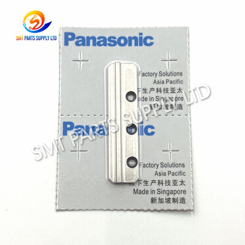
Panasonic 102031203702 Precision Guide for Automatic Insertion Machines

Brand Name: Panasonic
Model Number: 102031203702
Detail Information
Place of Origin:
CHINA&JAPEN
Product Name:
AI Insertion Machine Precision Guide
Brand:
Panasonic
Part Number:
102031203702
Part Description:
Guide
Product Category:
Automatic Insertion Machine Spare Part
Subcategory:
Mechanical Guide Component
Equipment Type:
AI Through-Hole Insertion Machine
Process Application:
Automatic Component Insertion
Main Function:
Guiding And Positioning Related Mechanical Movement
Applicable Machine:
Panasonic/Panasert AI Insertion Equipment, Subject To Verification
Referenced Series:
JVK-related Application; Other Configurations Must Be Confirmed
Installation Area:
Guide Or Insertion-related Mechanical Assembly
Product Structure:
Machine-specific Precision Mechanical Component
Material:
According To Actual Supplied Version
Product Description

Panasonic 102031203702 AI Insertion Machine Precision Guide

Panasonic 102031203702 Precision Guide for Automatic Insertion MachinesPanasonic 102031203702 Precision Guide for Automatic Insertion MachinesPanasonic 102031203702 Precision Guide for Automatic Insertion Machines

The Panasonic 102031203702 Guide is a precision mechanical spare part developed for automatic through-hole component insertion equipment. Installed within the corresponding guiding, cutting, feeding, or insertion-related assembly, the guide helps control the movement path of connected mechanical parts and supports repeatable positioning during continuous production.

A worn, damaged, contaminated, or incorrectly installed guide may cause unstable movement, abnormal friction, inconsistent component handling, or accelerated wear of nearby parts. Replacing the affected component with a correctly matched 102031203702 Guide can help restore the mechanical relationship between the guide, slide cam, guide plate, base, roller, cutter, pin, spring, and other associated parts.

This product is suitable for electronics manufacturers, PCB assembly factories, insertion-machine maintenance departments, equipment service companies, and spare-parts distributors. Because Panasonic AI machines may have different configurations, production years, and assembly revisions, customers should verify the original part number, machine model, installation position, dimensions, and old-part appearance before ordering.


Product Identification
Item Product Information
Brand Reference Panasonic
Part Number 102031203702
Part Name Guide
Product Type Precision Mechanical Guide
Equipment Category AI Automatic Insertion Machine
Process Type Through-Hole Component Insertion
Primary Function Mechanical Guidance and Positioning
Installation Type Machine-Specific Mechanical Installation
Product Condition Original New or Compatible New, Subject to Quotation
Supply Type Single Spare Part
Order Requirement Confirm Part Number and Installation Position
Inspection Appearance, dimensions, fit, and condition checked before shipment
Packaging Protective industrial export packaging
Warranty Subject to quoted product condition and sales agreement

Core Product Advantages
Advantage Customer Benefit
Exact Part-Number Identification Helps reduce incorrect purchasing and installation risk
Precision Guiding Function Supports controlled and repeatable mechanical movement
Maintenance-Oriented Supply Suitable for preventive maintenance and emergency repair
Stable Installation Helps maintain the intended relationship between connected parts
Inspection Before Dispatch Reduces the risk of visible damage or incorrect shipment
Multiple Supply Options Original and compatible versions may be quoted according to demand
Export Packaging Protects the component during international transportation
Technical Confirmation Support Old-part photos and machine information can be checked before quotation

Cause: Why the Guide Requires Inspection or Replacement

The guide works within a repetitive mechanical system. During production, it may be exposed to continuous movement, vibration, friction, dust, component fragments, lubricant residue, and installation stress. Even when the machine remains operational, gradual wear can reduce the consistency of the guiding surface or installation relationship.

The following conditions may indicate that the guide or its associated assembly requires inspection.

1. Long-Term Mechanical Wear

Repeated contact between moving components and the guide surface can gradually change the contact area. Uneven wear may affect the intended travel path and create additional clearance between connected parts.

2. Abnormal Friction

Insufficient lubrication, contaminated grease, foreign particles, or incorrect assembly can increase friction. Excessive resistance may create unstable movement, noise, vibration, or accelerated wear.

3. Guide Surface Damage

Scratches, dents, deformation, chipped edges, or impact marks can interfere with smooth movement. Damage may result from a component jam, incorrect maintenance, accidental tool contact, or improper storage.

4. Incorrect Installation

If the guide is installed in the wrong direction, tightened unevenly, or positioned without proper alignment, the connected mechanism may not move according to the original design path.

5. Contamination Around the Assembly

Dust, clipped lead fragments, oil residue, and small metal particles can collect around the guide and related mechanism. Contamination can prevent smooth sliding and create local wear.

6. Wear of Adjacent Parts

A damaged slide cam, guide plate, pin, roller, spring, cutter, bracket, or base may transfer abnormal force to the guide. Replacing only one part without checking the surrounding assembly may not solve the complete problem.

7. Machine Collision or Component Jam

Improperly supplied components, bent leads, incorrect material settings, or mechanical obstruction may cause sudden impact within the insertion mechanism. The guide should be inspected whenever a serious jam or collision occurs.


Common Symptoms and Recommended Checks
Production Symptom Possible Mechanical Cause Recommended Check
Irregular mechanical movement Worn or contaminated guiding surface Clean and inspect the guide
Increased operating noise Friction, looseness, or misalignment Check mounting and adjacent parts
Repeated component jams Unstable guidance or incorrect setup Inspect guide path and material settings
Visible vibration Excessive clearance or loose fasteners Check guide, pins, bracket, and base
Inconsistent insertion action Wear in the associated mechanism Inspect complete insertion assembly
Cutter-area interference Incorrect guide relationship or damaged cutter Check cutter, guide, cam, and plate
Metal particles near the mechanism Abnormal wear between moving surfaces Stop the machine and identify the wear source
Frequent replacement of nearby parts Unresolved alignment problem Check installation datum and guide condition
Reduced production stability Multiple mechanical issues Perform complete preventive maintenance
Abnormal resistance during manual movement Contamination, damage, or incorrect assembly Clean, inspect, and realign the mechanism

Solution: Restore the Mechanical Guiding Relationship

Replacing the 102031203702 Guide is intended to restore the original guiding and positioning relationship within the relevant mechanical assembly. A correct replacement should be combined with cleaning, inspection, alignment, and testing instead of being treated as an isolated part change.

Recommended Maintenance Solution
  1. Stop the equipment according to the factory safety procedure.
  2. Record the current machine alarms and production symptoms.
  3. Photograph the original installation position before disassembly.
  4. Check the old guide for scratches, deformation, looseness, and uneven wear.
  5. Inspect the slide cam, guide plate, base, cutter, pin, roller, spring, and bracket.
  6. Remove dust, lead fragments, grease residue, and other contamination.
  7. Compare the new guide with the removed part.
  8. Confirm the part number, profile, holes, orientation, and installation surfaces.
  9. Install the guide without forcing or modifying the component.
  10. Tighten the mounting hardware evenly according to the machine service procedure.
  11. Manually check the mechanism for smooth and interference-free movement.
  12. Perform low-speed testing before returning to normal production.
  13. Inspect sample PCB assemblies and through-hole components.
  14. Record the replacement date for preventive maintenance management.

What the Replacement Can Help Improve
Maintenance Objective Expected Result
Restore the mechanical travel path More controlled movement of related components
Reduce abnormal clearance Better mechanical positioning consistency
Reduce friction and interference Smoother operation after correct installation
Improve assembly stability Lower risk of guide-related movement errors
Protect connected parts Reduced secondary wear when the root cause is corrected
Support production recovery Faster restoration after confirmed guide failure
Improve maintenance planning Easier spare-parts management using an exact part number
Reduce purchasing mistakes Clear identification through 102031203702

The actual result depends on the condition of the complete mechanism. If the guide is not the only worn component, additional parts may also need to be replaced.


Specifications
Basic Specifications
Specification Description
Product Name AI Insertion Machine Guide
Brand Reference Panasonic
Part Number 102031203702
Component Category Precision Mechanical Spare Part
Main Function Guiding, locating, and supporting mechanical movement
Equipment Type Automatic Through-Hole Insertion Equipment
Installation Location Corresponding guide or insertion-related mechanical assembly
Surface Condition Clean and free from visible transportation damage
Dimensional Requirement Must match the original 102031203702 component
Machine Compatibility Confirm according to machine model and assembly revision
Replacement Method Direct mechanical installation after verification
Modification Requirement Modification is not recommended
Inspection Standard Part number, appearance, dimensions, mounting profile, and condition
Sales Unit Piece
MOQ One piece or according to quotation
Availability Subject to current stock
Delivery Time Confirmed according to order quantity and stock status
Packaging Anti-collision and moisture-resistant protective packaging
Commercial Specifications
Commercial Item Available Option
Product Condition Original new, compatible new, or other quoted condition
Sample Order Available subject to stock
Bulk Order Supported
International Shipping Supported
Shipping Method Courier, air freight, or customer-appointed forwarder
Payment Terms Confirmed in formal quotation
Inspection Photos Available before shipment upon request
Packaging Label Part number and quantity identification
Export Documents Commercial invoice and packing list available
Technical Confirmation Supported with photos and machine information
After-Sales Handling According to inspection result and sales agreement

Application

The 102031203702 Guide is intended for use in the maintenance of Panasonic/Panasert-type AI automatic insertion equipment. These machines are commonly used to install leaded electronic components into prepared PCB through-holes.

The guide is not a universal component. Its suitability depends on the exact machine series, mechanical assembly, part revision, and installation position.

Typical Industries
Industry Typical Production
Consumer Electronics Power boards, control boards, and appliance PCBs
Automotive Electronics Controllers, relay boards, and power modules
Industrial Equipment Automation controllers and drive boards
Power Supply Manufacturing Power conversion and distribution assemblies
Home Appliance Manufacturing Main control and interface boards
Communication Equipment Network and signal control assemblies
Lighting Electronics LED drivers and lighting control boards
Contract Electronics Manufacturing Mixed-volume PCB assembly services
Equipment Maintenance AI insertion-machine repair and overhaul
Spare-Parts Distribution International supply of insertion-machine components
Typical Through-Hole Components

Depending on the machine configuration and production process, automatic insertion equipment may process leaded electronic components such as:

Component Category Example Application
Axial Components Resistors and diodes
Radial Components Capacitors and similar leaded devices
Jumper Wires PCB electrical connections
Leaded Devices Components prepared for automatic insertion
Special Formed Components Application-dependent through-hole parts

The guide does not directly determine the complete component range. The machine model, insertion head, tooling, program, feeder system, and component specification determine the actual production capability.


Recommended Users

This product is suitable for:

  • PCB assembly factories operating automatic insertion lines.
  • Production engineers managing through-hole component processes.
  • Equipment maintenance teams responsible for AI machines.
  • Service companies repairing insertion and lead-processing equipment.
  • Electronics manufacturers preparing critical spare-parts inventories.
  • Overseas distributors supplying SMT and THT machine components.
  • Factories restoring used Panasonic/Panasert insertion equipment.
  • Buyers seeking an exact replacement identified by part number 102031203702.

Panasonic 102031203702 Precision Guide for Automatic Insertion MachinesPanasonic 102031203702 Precision Guide for Automatic Insertion MachinesPanasonic 102031203702 Precision Guide for Automatic Insertion Machines
How It Works

The guide provides a controlled mechanical reference for the movement of associated parts. During the machine cycle, connected mechanisms may slide, rotate, push, cut, position, or return according to the equipment program. The guide helps keep this movement within the intended path.

Operating Principle
Stage Mechanical Action Guide Function
1. Machine Preparation The insertion unit returns to its initial position Maintains the mechanical reference path
2. Component Supply Material enters the processing area Supports stable movement of the related mechanism
3. Lead Processing Leads may be positioned, formed, or cut Helps keep connected parts aligned
4. Component Positioning The component is prepared for PCB insertion Supports repeatable mechanical positioning
5. Insertion Cycle The machine places the component into the PCB Maintains controlled movement within the assembly
6. Return Movement The mechanism returns for the next cycle Supports smooth and repeatable travel
7. Continuous Production The cycle repeats at production speed Helps maintain long-term mechanical consistency
Relationship With Nearby Parts

The guide may operate as part of an assembly containing several mechanical components. Depending on the machine configuration, related items may include:

  • Slide cam.
  • Guide plate.
  • Guide base.
  • Cutter.
  • Fixed cutter.
  • Roller.
  • Pin.
  • Spring.
  • Lever.
  • Bracket.
  • Pusher.
  • Bending or lead-processing parts.
  • Fasteners and locating components.

When diagnosing a fault, these parts should be inspected as a complete mechanical system. A new guide cannot compensate for a badly worn pin, damaged cam, bent bracket, incorrect cutter, or loose base.


Installation Recommendations
Before Installation
Checkpoint Requirement
Part Number Confirm 102031203702
Part Name Confirm Guide
Machine Model Check the machine nameplate
Assembly Position Compare with the original installation
Old-Part Appearance Provide clear front, back, and side photographs
Dimensions Compare major dimensions and mounting locations
Adjacent Parts Check for damage and abnormal wear
Work Area Clean and organize the maintenance area
Machine Status Disconnect and secure power according to factory procedures
Documentation Follow the machine maintenance manual
During Installation
  • Do not hammer, grind, bend, drill, or modify the guide.
  • Do not force the part into an incorrect position.
  • Keep the contact and mounting surfaces clean.
  • Confirm the correct installation direction.
  • Check whether locating pins and fasteners are in good condition.
  • Tighten screws evenly.
  • Ensure the connected parts move freely.
  • Apply only the lubricant specified for the machine assembly.
  • Prevent loose tools or metal particles from remaining inside the equipment.
After Installation
  • Move the mechanism manually where the service procedure permits.
  • Check for interference, abnormal resistance, and excessive clearance.
  • Run the equipment at low speed.
  • Observe the guide and connected mechanism during several cycles.
  • Confirm that no abnormal noise or vibration is present.
  • Test with approved production materials.
  • Inspect the inserted components and PCB condition.
  • Gradually return the machine to normal production speed.

Installation should be completed by trained maintenance personnel familiar with automatic insertion equipment.


How to Choose the Correct 102031203702 Guide

Correct product selection is essential because similar guides may have only small visual or dimensional differences. A similar appearance does not guarantee interchangeability.

Step 1: Confirm the Complete Part Number

The required part number should be 102031203702. Avoid ordering according to the product name “Guide” alone because the equipment may contain several different guide components.

Step 2: Check the Original Part

Inspect the removed part for:

  • Engraved or printed identification.
  • Mounting-hole position.
  • External profile.
  • Guide-surface shape.
  • Width, length, and thickness.
  • Left-hand or right-hand orientation.
  • Contact marks and installation direction.
Step 3: Confirm the Machine Information

Provide:

  • Machine brand.
  • Machine model.
  • Machine serial number.
  • Manufacturing year, when available.
  • Assembly name.
  • Installation position.
  • Current alarm or production problem.
Step 4: Compare Photographs

Send clear photographs showing:

  1. The complete old part.
  2. The front side.
  3. The reverse side.
  4. The side profile.
  5. The installation position.
  6. The surrounding mechanical assembly.
  7. Any marking or label.
  8. A ruler or caliper measurement when necessary.
Step 5: Select the Required Condition
Product Option Recommended Situation
Original New Customers prioritizing original specification and traceability
Compatible New Cost-sensitive maintenance when an approved alternative is acceptable
Used or Refurbished Only when clearly quoted and accepted by the customer
Sample Verification Recommended when machine information is incomplete
Step 6: Confirm Related Parts

If the guide has severe wear, inspect the related slide cam, plate, base, cutter, roller, pins, springs, and brackets. Replacing related worn components together may provide a more stable maintenance result.


Information Required for a Fast Quotation
Required Information Example
Part Number 102031203702
Part Name Guide
Quantity 1 piece, 5 pieces, or planned annual quantity
Product Condition Original new or compatible new
Machine Model Photograph of machine nameplate preferred
Old-Part Photos Front, back, side, and installation position
Destination Country Required for shipping quotation
Delivery Requirement Standard delivery or urgent shipment
Trade Terms EXW, FOB, CIF, or courier delivery as requested
Other Parts Send a complete inquiry list for combined shipment

Providing complete information allows the supplier to confirm the product more efficiently and reduces repeated communication.


Quality Control

Each supplied guide should be checked according to the agreed product condition and order requirement.

Incoming and Pre-Shipment Inspection
Inspection Item Inspection Purpose
Part-Number Verification Prevent incorrect item shipment
Product-Name Verification Confirm the component is a guide
Appearance Inspection Identify scratches, deformation, rust, or impact damage
Mounting-Profile Check Confirm the installation structure
Major Dimension Check Compare with available sample or technical information
Surface Check Confirm that guiding surfaces are clean and usable
Quantity Check Ensure the ordered quantity is correct
Packaging Check Prevent movement and collision during transport
Label Check Clearly identify part number and quantity
Photo Record Provide shipment reference when requested
Important Quality Note

Dimensional tolerances, material grade, hardness, coating, and detailed engineering specifications are dependent on the actual production version. Buyers requiring these data should provide a drawing, sample, or formal technical requirement before placing an order.


Packaging and Shipping

The 102031203702 Guide is a precision mechanical component and should be protected from impact, moisture, contamination, and uncontrolled movement during transportation.

Standard Packaging Process
  1. Clean visual inspection.
  2. Individual protective wrapping.
  3. Moisture-resistant inner packaging.
  4. Anti-collision cushioning.
  5. Part-number identification label.
  6. Strong export carton.
  7. Outer shipping label.
  8. Final quantity verification.
Shipping Options
Shipping Method Suitable Order
International Express Samples and urgent spare parts
Air Freight Medium-volume urgent shipments
Sea Freight Large combined orders
Customer Forwarder Buyers with appointed logistics partners
Combined Shipment Multiple machine parts in one order

Shipping cost and delivery time depend on destination, quantity, package size, customs procedures, and the selected transport method.


Inventory and Spare-Parts Planning

Production lines can experience substantial downtime when a small mechanical part is unavailable. Buyers operating older AI insertion equipment should establish a spare-parts plan based on machine quantity, operating hours, maintenance history, and local delivery time.

Suggested Inventory Categories
Inventory Level Recommended Parts
Emergency Stock Guides, cutters, pins, springs, rollers, and sensors
Preventive Maintenance Stock Wear parts with known replacement cycles
Repair Stock Mechanical assemblies used after collision or jamming
Long-Lead-Time Stock Discontinued or difficult-to-source components
Multi-Machine Stock Common parts used across several production lines

The required quantity should be determined by the factory maintenance team. No universal replacement interval can be applied to every machine because wear depends on production volume, material condition, maintenance quality, and equipment configuration.


Why Purchase From a Specialized AI Spare-Parts Supplier
Exact Part-Number Handling

Industrial buyers usually need a specific component rather than a general product category. We organize inquiries using the exact part number to support faster identification.

Machine-Information Confirmation

Customers can submit machine labels, old-part photographs, dimensions, and installation-position images for checking before order placement.

Original and Compatible Options

Different factories have different budgets and maintenance requirements. Available product conditions can be quoted separately for comparison.

Support for Mixed Spare-Parts Orders

Buyers can combine guides, cutters, cams, plates, pins, springs, rollers, belts, sensors, motors, boards, valves, and other machine parts into one inquiry.

International Supply Experience

Protective packaging, part-number labels, commercial invoices, packing lists, and international shipping options can be arranged for overseas customers.

Production-Line-Oriented Service

Our objective is not only to provide a part number but also to help customers reduce selection errors, shorten maintenance communication, and restore production efficiently.


Frequently Asked Questions
Q1: What is Panasonic part number 102031203702?

A: Part number 102031203702 is identified as a mechanical Guide used in Panasonic/Panasert AI automatic insertion-machine equipment. It belongs to the guide and insertion-related mechanical parts category. The exact installation position should be confirmed using the removed part, machine model, and assembly photographs.

Q2: Which machine models use the 102031203702 Guide?

A: Public spare-parts listings associate this guide with Panasonic/Panasert automatic insertion-machine applications, including JVK-related parts listings, while some suppliers also reference AV131 equipment. Because configurations and revisions may differ, the machine model alone should not be used as the only compatibility standard. Please confirm the original part number and installation position.

Q3: Is this guide supplied as an original part or a compatible replacement?

A: Original-new and compatible-new supply options may be available. Availability depends on current inventory and the requested quantity. The formal quotation will clearly state the offered product condition so the buyer can select the appropriate option.

Q4: What information should I send before ordering?

A: Please provide part number 102031203702, required quantity, preferred product condition, machine model, machine serial number when available, old-part photographs, installation-position photographs, and the destination country. Dimensions are recommended when the existing part has no visible identification.

Q5: Can the guide be installed without replacing other parts?

A: It can be replaced individually when the surrounding components remain in good condition. However, severe guide wear may indicate problems with the cam, plate, base, cutter, roller, pin, spring, bracket, or alignment. Inspecting the complete mechanism before installation is strongly recommended.


Contact Us

Looking for the Panasonic 102031203702 AI Insertion Machine Guide?

Please send us the following information for a fast and accurate quotation:

  • Required part number.
  • Required quantity.
  • Original-new or compatible-new requirement.
  • Machine model and serial number.
  • Clear photographs of the old guide.
  • Photographs of the installation position.
  • Destination country and postal code.
  • Required delivery schedule.
  • Complete spare-parts inquiry list, if available.

We supply automatic insertion-machine spare parts for maintenance, production restoration, preventive replacement, and international distribution.

Contact us today to check stock, compare available product conditions, receive inspection photographs, and obtain an export quotation.

Important Compatibility Notice:
Panasonic and related machine names are used only to identify product compatibility and the referenced spare-part application. Buyers should verify the part number, machine configuration, dimensions, and installation position before purchase. Product availability, condition, warranty, and delivery time are subject to the final quotation.