logo
Good price  online

products details

Created with Pixso. Home Created with Pixso. Products Created with Pixso.
SMT Machine Parts
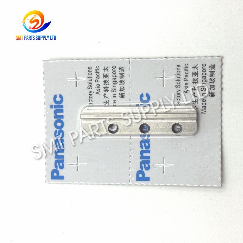
Created with Pixso. Panasonic 102031203802 JVK Guide(R) Right-Side Mechanical Guide Component for Automatic Insertion Machines

Panasonic 102031203802 JVK Guide(R) Right-Side Mechanical Guide Component for Automatic Insertion Machines

Brand Name: Panasonic
Model Number: 102031203802
Detail Information
Place of Origin:
CHINA&JAPEN
Brand:
Panasonic
Product Model:
102031203802
Part Number:
102031203802
Product Name:
JVK Guide(R)
Alternative Description:
Right-Side Mechanical Guide
Product Category:
Automatic Insertion Machine Spare Part
Equipment Category:
AI / THT Insertion Equipment
Applicable Machine:
JVK Automatic Insertion Machine
Installation Position:
Right-side Guide Position
Main Function:
Mechanical Guidance And Positioning
Operating Function:
Supports Controlled Repetitive Movement
Drive Type:
Passive Mechanical Component
Electrical Component:
No
Pneumatic Component:
No
Mechanical Component:
Yes
Product Description

Panasonic 102031203802 JVK Guide(R) AI Insertion Machine Spare Part

Panasonic 102031203802 JVK Guide(R) Right-Side Mechanical Guide Component for Automatic Insertion MachinesPanasonic 102031203802 JVK Guide(R) Right-Side Mechanical Guide Component for Automatic Insertion MachinesPanasonic 102031203802 JVK Guide(R) Right-Side Mechanical Guide Component for Automatic Insertion Machines

The Panasonic 102031203802 Guide(R) is a mechanical guide component identified for JVK automatic insertion equipment. It is installed within the machine’s operating mechanism to support controlled component movement, maintain the intended travel path, and help associated parts remain correctly positioned during repetitive insertion cycles.

Public spare-parts references identify 102031203802 as a JVK GUIDE, with some component lists describing it specifically as GUIDE(R), indicating a right-side guide configuration. It is commonly listed together with 102031203702, guide plates, sliders, pushers, pins, rollers, cams, cutters, and other parts used in automatic insertion mechani

The guide is suitable for maintenance projects involving worn, damaged, deformed, contaminated, or incorrectly aligned guide components. Correct replacement can help restore stable movement, reduce abnormal friction, support repeatable positioning, and prevent unnecessary contact between adjacent mechanical parts.

Because automatic insertion equipment may have different revisions, configurations, or installation positions, buyers should verify the part number, orientation, machine model, physical dimensions, and old-part appearance before placing an order.


Core Product Information

Item Description
Product Name JVK Guide(R)
Part Number 102031203802
Product Type Mechanical Guide Component
Orientation Right-Side Guide / Guide(R)
Equipment Category Automatic Insertion Machine
Primary Application JVK Insertion Mechanism
Part Category AI Machine Spare Part
Installation Function Guidance, positioning and movement support
Supply Condition New, original or compatible version subject to confirmation
Ordering Unit Piece
Inspection Requirement Part number, appearance and dimensions checked before shipment
Purchase Verification Machine model, old-part photo and installation position recommended

Product Function

The primary purpose of the 102031203802 Guide(R) is to provide a controlled mechanical path for related moving components inside the insertion unit.

During continuous production, the associated mechanism operates at repeated speed and frequency. A correctly installed guide helps maintain the required motion direction and positional relationship between sliders, cams, pushers, cutters, pins, rollers, and other cooperating components.

Its functional responsibilities may include:

Function Practical Value
Movement Guidance Helps associated parts move along the intended mechanical path
Positional Support Maintains the relative position of cooperating components
Side Alignment Supports right-side alignment within the JVK mechanism
Motion Stability Reduces unnecessary side movement during repetitive operation
Friction Control Helps prevent irregular contact caused by poor alignment
Cycle Repeatability Supports consistent mechanical action during continuous production
Component Protection Reduces the risk of secondary damage to nearby parts
Maintenance Recovery Helps restore the operating condition of a worn guide assembly

The guide should not be selected only by general appearance. Two guide components may look similar while having different hole positions, profiles, thicknesses, orientations, or installation relationships.


Cause: Why the Guide Requires Replacement

Automatic insertion machines depend on precise and repetitive mechanical movement. The guide may gradually wear or become damaged because of long operating hours, contamination, insufficient lubrication, incorrect adjustment, abnormal impact, or wear in neighboring components.

1. Long-Term Mechanical Wear

Continuous sliding or contact may gradually change the guide surface. Even minor wear can increase clearance and affect the motion path of the cooperating mechanism.

2. Incorrect Mechanical Alignment

If the slider, cam, pusher, cutter, base, or mounting position is misaligned, uneven force may be applied to the guide. This can result in local wear, scratches, deformation, or abnormal resistance.

3. Dust and Process Contamination

Metal particles, component lead fragments, oil residue, dust, and production debris can enter the guide area. Contaminants may increase friction and accelerate wear.

4. Insufficient or Incorrect Lubrication

Some cooperating mechanical surfaces require controlled lubrication. Insufficient lubrication can increase friction, while excessive or unsuitable lubricant may collect dust and debris.

5. Abnormal Machine Impact

A component jam, incorrect setup, damaged cutter, displaced slider, or unexpected collision can transfer impact force to the guide and its mounting area.

6. Loose Fasteners

Loose mounting hardware can allow the guide to move from its intended position. Continued operation may damage the mounting holes, adjacent parts, or guide profile.

7. Worn Cooperating Components

Installing a new guide without inspecting associated sliders, pins, rollers, cams, pushers, and cutters may result in repeated failure. Wear frequently develops across several connected components rather than in one isolated part.


Common Symptoms of Guide Wear or Damage

Machine Symptom Possible Guide-Related Cause
Irregular mechanical movement Guide surface worn, contaminated or damaged
Increased operating resistance Misalignment, debris or surface damage
Repeated component jamming Incorrect guide position or worn mating parts
Abnormal mechanical noise Excessive clearance or irregular contact
Unstable insertion action Guide no longer maintaining the correct motion path
Uneven wear on sliders or pushers Guide alignment or mounting issue
Frequent stoppage Mechanism unable to complete a stable operating cycle
Visible scratches or deformation Impact, contamination or extended service wear
Loose movement in the mechanism Increased clearance around the guide assembly
Reduced production consistency Mechanical positioning no longer repeatable

These symptoms may also result from other parts. A complete inspection should therefore include the guide, guide plate, slider, cam, cutter, pusher, roller, pin, spring, base, fasteners, and mounting surface.


Solution: Replacing the 102031203802 Guide(R)

Replacing a worn or damaged guide can help restore the intended motion relationship within the JVK mechanism.

The recommended maintenance process is not simply to remove the old part and install a new one. The technician should inspect the complete assembly, identify the original reason for failure, clean the installation area, and confirm the movement of all cooperating components.

Recommended Replacement Procedure

Step Maintenance Action
1 Stop the machine according to the equipment safety procedure
2 Disconnect power and isolate pneumatic or mechanical energy
3 Record the original guide position and installation direction
4 Photograph the assembly before disassembly
5 Remove covers and interfering components carefully
6 Inspect the guide, slider, cam, pusher, cutter, pins and rollers
7 Clean the mounting area and remove particles or residue
8 Compare the old guide with part number 102031203802
9 Confirm right-side orientation and mounting-hole alignment
10 Install the replacement guide without forcing the part
11 Tighten mounting hardware according to maintenance requirements
12 Check movement manually before restoring full operation
13 Run the mechanism at low speed or in maintenance mode
14 Verify smooth travel, clearance, alignment and repeatability
15 Resume production only after stable operation is confirmed

Maintenance Result

  • Restore a stable mechanical movement path.
  • Reduce abnormal side clearance.
  • Improve alignment between cooperating components.
  • Reduce irregular friction and mechanical noise.
  • Support consistent insertion cycles.
  • Protect sliders, cams, cutters, pushers, and pins.
  • Reduce repeated stoppages caused by guide-area resistance.
  • Improve maintenance reliability and spare-parts planning.

Specifications

Specification Details
Brand Reference Panasonic
Part Number 102031203802
Standard Part Name GUIDE
Detailed Identification GUIDE(R)
Equipment Series JVK automatic insertion equipment
Equipment Type Radial or automatic component insertion machine
Component Type Mechanical motion guide
Installation Side Right side
Mechanical Function Guide and positioning support
Operating Mode Repetitive mechanical movement
Mounting Method Machine-specific mechanical installation
Material Confirm according to actual supplied version
Surface Treatment Confirm according to actual supplied version
Dimensions Confirm using old part, drawing or measured sample
Electrical Function None
Pneumatic Function None
Consumable Type Wear-related mechanical replacement part
Recommended Check Part number, direction, dimensions and mounting position
Packaging Protective bag, foam and export carton
Minimum Order Quantity Subject to stock and quotation
Delivery Time Subject to inventory and order quantity
Quality Inspection Appearance, part number and dimensional comparison
Warranty Subject to supply condition and sales agreement

Important Specification Notice

Detailed dimensions, material grade, hardness, coating, surface roughness, and installation tolerance should not be assumed from the product name alone.

To obtain accurate confirmation, provide:

  1. A clear photograph of the complete old guide.
  2. A close-up photograph of both sides.
  3. The machine model and serial number.
  4. The installation position.
  5. Measured length, width, thickness, and hole spacing.
  6. Photographs of the surrounding assembly.
  7. Required quantity and expected delivery date.

Related Components for Inspection

Part number 102031203802 is listed in JVK parts groups together with components such as guide 102031203702, sliders, guide plates, pushers, rollers, pins, cams, and cutt

When replacing the guide, inspect the following parts where applicable:

Related Component Inspection Point
102031203702 Guide Left-side condition, wear and alignment
Slider Surface wear, free movement and side clearance
Guide Plate Flatness, mounting condition and contact marks
Cam Profile wear, rotation and surface damage
Pusher Straightness, contact surface and movement
Cutter Edge condition, alignment and interference
Roller Rotation, wear and bearing condition
Pin Bending, looseness and surface damage
Spring Elasticity, deformation and installation
Mounting Base Flatness, contamination and thread condition
Fasteners Tightness, damage and correct installation
Lubrication Area Lubricant condition and contamination

Replacing all parts is not always necessary. However, associated components should be checked to prevent a damaged mating part from causing premature wear on the new guide.


Application

The Panasonic 102031203802 Guide(R) is intended for maintenance and repair of JVK automatic insertion machine mechanisms.

Typical Application Environments

Application Environment Use of the Guide
PCB Assembly Factory Supports automatic through-hole component insertion equipment
Electronics Manufacturing Services Used during preventive and corrective machine maintenance
Automotive Electronics Production Helps maintain stable insertion equipment operation
Power Supply Manufacturing Supports production of boards with leaded components
Industrial Control Production Used in automatic insertion lines for through-hole assemblies
Home Appliance Electronics Supports high-volume PCB insertion processes
Machine Refurbishment Replaces worn or damaged parts during equipment rebuilding
Spare-Parts Inventory Stored as a maintenance spare for older production equipment
Technical Service Company Used for customer machine repair and inspection
Production-Line Recovery Helps reduce downtime following mechanical guide failure

Suitable Purchasing Situations

This product is suitable for customers who:

  • Have confirmed the old part number as 102031203802.
  • Require a right-side JVK guide component.
  • Are repairing an automatic insertion mechanism.
  • Have identified wear, scratches, deformation, or excess clearance.
  • Need maintenance stock for discontinued or mature equipment.
  • Operate multiple insertion machines and require spare-parts support.
  • Need an old part to be matched by photographs and measurements.
  • Require consolidated shipment with other AI machine parts.

Panasonic 102031203802 JVK Guide(R) Right-Side Mechanical Guide Component for Automatic Insertion MachinesPanasonic 102031203802 JVK Guide(R) Right-Side Mechanical Guide Component for Automatic Insertion MachinesPanasonic 102031203802 JVK Guide(R) Right-Side Mechanical Guide Component for Automatic Insertion Machines

How It Works

The guide operates as a passive mechanical positioning component. It does not create electrical, pneumatic, or motor-driven movement by itself.

Instead, the guide works together with the machine’s moving mechanism.

Operating Sequence

  1. The machine initiates an insertion cycle.
  2. A driven component such as a cam, slider, lever, or actuator begins moving.
  3. The related moving part follows the path controlled by the guide assembly.
  4. The guide helps limit unwanted side movement.
  5. Cooperating components remain in the required positional relationship.
  6. The insertion, cutting, forming, or return action is completed.
  7. The mechanism returns to its starting position.
  8. The process repeats during the next production cycle.

Functional Relationship

Machine Action Guide Contribution
Initial movement Supports correct travel direction
Sliding action Maintains the intended mechanical path
Load transfer Helps distribute contact in the designed position
Cutting or forming cycle Supports alignment of cooperating parts
Return movement Helps the mechanism return without irregular side movement
Repeated operation Maintains cycle-to-cycle positioning consistency

A worn guide may allow the associated part to tilt, shift, vibrate, or contact another component. This can increase resistance and reduce the repeatability of the mechanism.


Product Advantages

1. Correct Part-Number Identification

The product is supplied under part number 102031203802, allowing buyers to compare it directly with maintenance records, equipment parts lists, or old-component markings.

2. Right-Side Guide Configuration

The GUIDE(R) identification helps distinguish it from associated left-side or differently oriented guide components.

3. Designed for Repetitive Mechanical Operation

The component is intended for a machine mechanism that performs repeated operating cycles and requires stable positional guidance.

4. Supports Accurate Mechanical Alignment

A correctly installed guide helps cooperating parts remain within the designed operating path.

5. Suitable for Preventive Maintenance

The guide can be held as a spare part for planned maintenance, reducing delays when the original component becomes worn.

6. Suitable for Corrective Repair

It can be used when troubleshooting abnormal movement, guide-area wear, interference, or mechanical instability.

7. Easy Identification by Photos and Measurements

Customers can submit old-part images and dimensions for comparison before shipment.

8. Protective Export Packaging

The product can be individually protected to reduce collision, scratching, contamination, and movement during international transport.


How to Choose

Selecting the correct guide requires more than checking the general product name.

Step 1: Confirm the Complete Part Number

Check that the old part, machine manual, maintenance record, or bill of materials shows:

102031203802

Avoid ordering according to an incomplete number such as 1020312038 unless all other information has been verified.

Step 2: Confirm the Orientation

This product is identified as Guide(R) in relevant parts references. Confirm that the required installation position is the right-side guide.

Do not confuse it with:

  • 102031203702 Guide.
  • A left-side guide.
  • A guide plate.
  • A slider.
  • A guide base.
  • A lead guide.
  • A guide pin.
  • A guide chuck.

Step 3: Confirm the Machine

Provide the complete machine model, serial number, production year, and equipment configuration.

The most reliable confirmation is based on:

Verification Method Reliability
Complete part number High
Machine parts manual High
Old-part photograph High
Dimensional drawing High
Installation-position photograph High
Machine model only Medium
Product appearance only Low
General product name only Low

Step 4: Compare Physical Details

Compare the following details before ordering:

  • Overall length.
  • Overall width.
  • Thickness.
  • Hole quantity.
  • Hole diameter.
  • Hole spacing.
  • Edge profile.
  • Groove position.
  • Contact surface.
  • Installation direction.
  • Left/right orientation.
  • Surface finish.
  • Markings or engraved numbers.

Step 5: Select the Required Supply Condition

Confirm whether your project requires:

  • Original new part.
  • New compatible part.
  • Reconditioned part.
  • Sample-based custom production.
  • Emergency stock item.
  • Batch purchasing for maintenance inventory.

Availability may vary. The required condition should be clearly written in the inquiry.

Step 6: Inspect Related Parts

If the old guide failed because of a damaged slider, cam, pusher, cutter, pin, or mounting base, replacing only the guide may not solve the problem.

Provide photos of the complete mechanism when abnormal wear is visible.


Original, Compatible and Sample-Based Supply Options

Supply Option Suitable Requirement
Original New Customers requiring verified original supply condition
New Compatible Cost-sensitive maintenance with confirmed specifications
Sample-Based Production Older parts without reliable local inventory
Drawing-Based Production Projects with complete dimensional and technical drawings
Complete Mechanism Set Customers replacing several worn cooperating parts
Mixed Spare-Parts Order Customers consolidating multiple AI machine parts

All supply options are subject to technical confirmation, inventory status, quantity, and quotation.

The use of a brand name or machine model in this description is intended to identify product compatibility and application. It does not imply affiliation unless the supplied product is specifically confirmed as an original branded part.


Quality Control

Each order should be checked according to the confirmed supply condition.

Recommended Inspection Items

Inspection Item Inspection Content
Part Number Verify 102031203802
Product Name Verify GUIDE / GUIDE(R)
Orientation Confirm right-side configuration
Appearance Check for scratches, dents, rust or deformation
Dimensions Compare with sample, drawing or confirmed measurements
Mounting Holes Check quantity, diameter, spacing and condition
Guide Profile Confirm shape and working surface
Surface Condition Check contact and sliding areas
Packaging Confirm individual protection and export carton
Quantity Verify against purchase order
Photographic Record Available when requested before shipment

Pre-Shipment Confirmation

For special or low-volume mechanical parts, pre-shipment photographs can be used to confirm:

  • Overall appearance.
  • Front and rear views.
  • Left and right sides.
  • Mounting holes.
  • Product quantity.
  • Packaging condition.
  • Part number labels.
  • Comparison with the customer’s reference photo.

Packaging and Shipping

Mechanical guide components should be protected from impact, contamination, moisture, and movement during transportation.

Standard Packaging Process

  1. The part is visually inspected.
  2. The working surface is cleaned when required.
  3. The product is packed in a protective bag.
  4. Foam or cushioning material is added.
  5. The component is placed in an inner box.
  6. The inner box is packed in an export carton.
  7. Shipping labels and order information are checked.
  8. Reinforced packaging is used for combined or heavy orders.

Available Shipping Methods

Shipping Method Suitable Order
International Express Samples and urgent spare-parts orders
Air Freight Medium-volume, time-sensitive orders
Sea Freight Large consolidated shipments
Customer Courier Account Buyers with an existing logistics account
Combined Shipment Multiple spare parts purchased together

Delivery time depends on stock availability, product condition, order quantity, payment confirmation, destination, and shipping method.


Storage Recommendations

To keep the guide in usable condition before installation:

  • Store it in a clean and dry environment.
  • Keep it inside the original protective packaging.
  • Avoid direct contact with moisture or corrosive chemicals.
  • Do not place heavy products on top of the guide.
  • Prevent collision with cutters, pins, or other metal parts.
  • Label the part number clearly.
  • Separate right-side and left-side components.
  • Use first-in, first-out inventory control.
  • Inspect stored parts periodically.
  • Keep sample photographs and dimensions in the maintenance database.

Installation Notes

Installation should be completed by trained maintenance personnel familiar with automatic insertion equipment.

Before Installation

  • Stop the machine safely.
  • Isolate all energy sources.
  • Clean the working area.
  • Prepare suitable tools.
  • Review the original installation position.
  • Check the replacement part against the old guide.
  • Confirm right-side orientation.
  • Inspect the mounting surface.
  • Check related mechanical components.

During Installation

  • Do not force the guide into position.
  • Do not modify mounting holes without engineering approval.
  • Avoid hitting the guide with hard tools.
  • Keep the contact surface clean.
  • Confirm the correct installation direction.
  • Tighten fasteners evenly.
  • Check that nearby parts are not trapped or displaced.
  • Apply only the specified lubricant where required.

After Installation

  • Move the mechanism manually where permitted.
  • Confirm that no abnormal resistance is present.
  • Check the clearance between cooperating parts.
  • Run the machine at low speed.
  • Observe several complete cycles.
  • Listen for abnormal noise.
  • Check for vibration or side movement.
  • Confirm stable production before full-speed operation.

Frequently Asked Questions

Q1: What is Panasonic 102031203802?

Panasonic 102031203802 is identified as a JVK mechanical guide component used in an automatic insertion machine mechanism. Some spare-parts lists describe it as GUIDE(R), indicating the right-side guide. It supports controlled movement, alignment, and positioning of cooperating mechanical components.

Q2: Is 102031203802 interchangeable with 102031203702?

They should not be assumed to be interchangeable. The two numbers are listed as separate guide components and may represent different sides, profiles, or installation positions. Confirm the orientation, mounting holes, dimensions, old-part photographs, and machine parts manual before ordering.

Q3: Which machine uses the 102031203802 guide?

The part is commonly identified in JVK automatic insertion machine spare-parts lists. Because equipment revisions and mechanical configurations may differ, provide the complete machine model, serial number, old-part photograph, and installation-position photograph for final compatibility confirmation.

Q4: What information is required for a quotation?

Please provide part number 102031203802, required quantity, machine model, old-part photographs, installation position, preferred supply condition, delivery destination, and expected delivery date. Dimensions are strongly recommended when the old part has no clear marking.

Q5: Can you supply related JVK mechanical parts?

Related mechanical parts may include guide 102031203702, guide plates, sliders, cams, pushers, cutters, pins, rollers, springs, bases, and mounting components. Send a complete parts list or photographs so the required items can be checked together.


Why Purchase From Us

Professional AI Machine Parts Support

We focus on spare parts used in PCB assembly, automatic insertion, SMT, screen printing, conveying, and related electronics manufacturing equipment.

Part-Number-Based Identification

Orders are checked using part numbers, machine models, photographs, dimensions, and installation positions to reduce selection errors.

Flexible Supply Options

Original new, compatible, sample-based, and drawing-based supply options may be available according to the customer’s technical and budget requirements.

Small-Quantity Support

Single-piece and small maintenance orders can be handled according to inventory and product availability.

Consolidated Purchasing

Customers can combine guides, cutters, sliders, cams, pins, rollers, sensors, valves, motors, boards, feeders, and other machine parts in one shipment.

Export Packaging

Products are packed with suitable protection for international express, air freight, or consolidated export shipment.

Pre-Shipment Verification

Photos, labels, quantities, and packaging information can be provided for confirmation when requested.


Contact Us

Looking for Panasonic 102031203802 JVK Guide(R) or other automatic insertion machine spare parts?

Send us the following information to receive a faster and more accurate quotation:

Required Information Example
Part Number 102031203802
Product Name JVK Guide(R)
Machine Model Complete model shown on machine nameplate
Required Quantity 1 piece, 5 pieces or maintenance quantity
Supply Condition Original new or compatible
Old-Part Photos Front, back, sides and mounting area
Dimensions Length, width, thickness and hole spacing
Delivery Destination Country, city or postal code
Delivery Requirement Standard or urgent
Related Parts Additional guides, sliders, cutters or pins

Clear photographs and complete machine information can significantly improve confirmation accuracy.

Contact us today for:

  • Stock checking.
  • Technical identification.
  • Part-number matching.
  • Related-parts recommendations.
  • Bulk-order quotations.
  • International shipping options.
  • Maintenance spare-parts support.