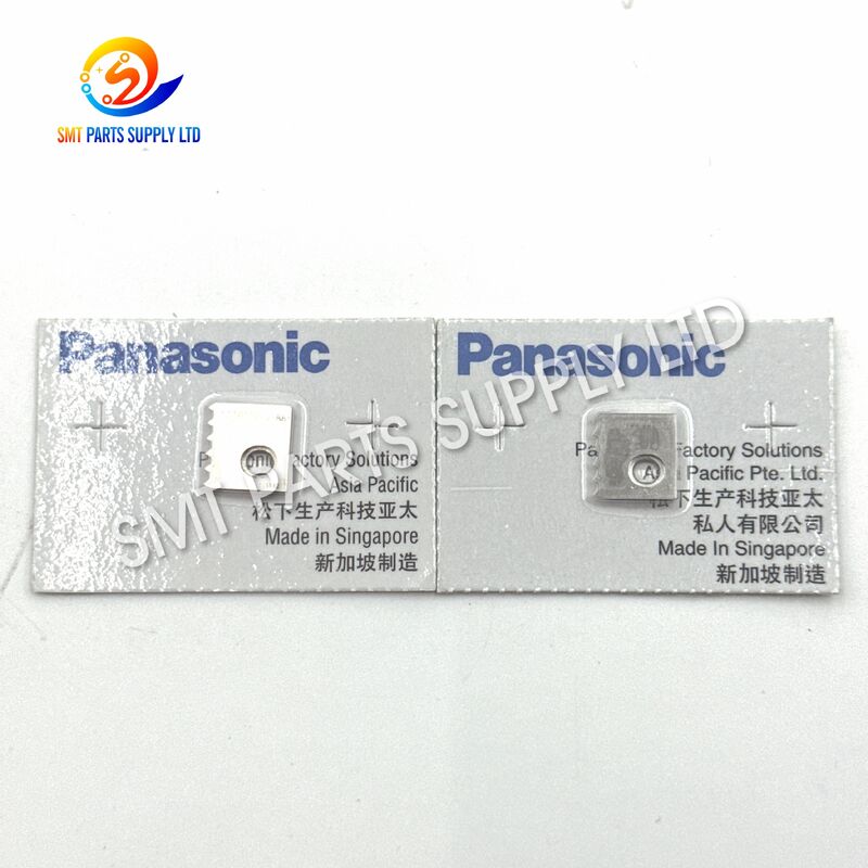
| Brand Name: | Panasonic |
| Model Number: | N210124716AA |
The Panasonic N210124716AA Lead Guide (A) is a precision mechanical component used in compatible Panasonic AI component insertion equipment. Installed within the lead handling or insertion mechanism, the guide helps control the travel path and positioning of component leads before or during the insertion process. Accurate lead guidance is important for maintaining stable feeding, correct alignment, and repeatable component placement.
When the original guide becomes worn, bent, scratched, contaminated, or incorrectly positioned, lead movement may become unstable. This can cause component lead deviation, insertion errors, production interruptions, or accelerated wear on nearby parts. Replacing the damaged guide with a correctly matched N210124716AA component can help restore smooth mechanical movement and reliable machine operation.
Public spare-parts listings identify N210124716AA as a Panasonic Lead Guide (A), Guide, or AI insertion-machine accessory. Exact machine compatibility should always be confirmed using the equipment parts manual, installed sample, and complete part number before ordering. 4search4turn766994search22
| Benefit | Customer Value |
|---|---|
| Precision Lead Guidance | Helps keep component leads moving through the correct mechanical path |
| Stable Insertion Alignment | Supports repeatable lead positioning before insertion |
| Reduced Lead Deviation | Helps minimize side movement, bending, and incorrect lead entry |
| Smooth Mechanical Operation | Reduces unnecessary resistance in the guiding section |
| Maintenance-Friendly Replacement | Suitable for scheduled maintenance and repair work |
| Durable Metal Construction | Designed for repeated mechanical contact in production equipment |
| Part Number Identification | Clearly identified by N210124716AA for purchasing control |
| Lower Downtime Risk | Timely replacement helps prevent unexpected production interruptions |
| Consistent Production Support | Helps maintain stable insertion quality over repeated operating cycles |
| Easy Purchasing Verification | Can be checked using the old part, machine manual, and installed position |
A lead guide operates in a mechanical area where component leads, moving assemblies, and surrounding machine parts may create repeated contact. Over time, normal production conditions can gradually change the guide surface or its installed alignment.
The guide may appear small, but its condition can directly influence the movement of component leads. Even minor wear or deformation can affect the lead path and create unstable insertion performance.
| Cause | Description | Possible Production Effect |
|---|---|---|
| Long-Term Mechanical Wear | Repeated contact gradually wears the guiding surface | Increased clearance and unstable lead positioning |
| Bent or Deformed Guide | Impact, incorrect handling, or machine collision changes the guide shape | Lead deviation or insertion failure |
| Surface Scratches | Hard particles or damaged leads mark the contact surface | Increased friction and irregular movement |
| Material Residue | Dust, oil, lead fragments, or production contamination collects around the guide | Restricted movement or inconsistent feeding |
| Incorrect Installation | The part is not seated or tightened correctly | Misalignment and abnormal wear |
| Worn Adjacent Components | Nearby cutters, holders, cams, or guide parts develop excessive clearance | Uneven load on the lead guide |
| Improper Maintenance | Cleaning or adjustment is performed with unsuitable tools | Surface damage or dimensional change |
| Wrong Replacement Part | A visually similar but incompatible guide is installed | Poor fit and unstable machine operation |
| Component Lead Variation | Incorrect or damaged incoming components increase contact pressure | Accelerated guide wear |
| Machine Timing Error | The guide and related mechanism move out of sequence | Collision or repeated mechanical stress |
Operators and maintenance technicians should inspect the N210124716AA Lead Guide (A) when the machine shows one or more of the following symptoms:
| Machine Symptom | Possible Relationship to the Guide |
|---|---|
| Component leads do not enter the expected path | Guide position or surface may be worn |
| Leads bend during the insertion cycle | Guide clearance or alignment may be incorrect |
| Intermittent insertion alarms occur | Lead movement may not be repeatable |
| Components are rejected without an obvious electrical cause | Mechanical guidance should be inspected |
| Abnormal marks appear on component leads | Guide surface may be scratched or damaged |
| Lead movement becomes slow or inconsistent | Dirt or excessive friction may be present |
| The machine requires frequent manual adjustment | Guide or neighboring parts may have excessive wear |
| Unusual mechanical noise appears near the insertion mechanism | The guide may be contacting another moving part |
| Production quality changes after a collision | The guide may have become bent or displaced |
| Repeated faults occur with otherwise acceptable components | The lead path should be checked |
These symptoms may also be caused by cutters, insertion chucks, holders, sensors, cams, springs, or feeding mechanisms. The complete assembly should therefore be inspected before replacing only one component.
Replacing a damaged or excessively worn lead guide restores the intended mechanical path for component leads. A correctly installed guide helps the lead enter the insertion area at a controlled angle and position.
The replacement process should include cleaning, alignment inspection, adjacent-part inspection, and a controlled production test. Simply installing a new guide without checking the surrounding mechanism may not fully solve the original problem.
| Step | Recommended Action | Purpose |
|---|---|---|
| 1 | Stop the machine and follow the correct safety procedure | Prevent accidental machine movement |
| 2 | Record the alarm, symptom, and affected station | Improve fault diagnosis |
| 3 | Inspect the installed guide visually | Identify wear, bending, scratches, or contamination |
| 4 | Confirm the complete part number N210124716AA | Avoid ordering a similar but incorrect guide |
| 5 | Compare the old part with the replacement | Verify shape, mounting points, and orientation |
| 6 | Clean the mounting surface and surrounding area | Prevent alignment errors caused by debris |
| 7 | Check adjacent cutters, holders, cams, and guide parts | Identify additional sources of abnormal wear |
| 8 | Install the replacement according to the service procedure | Maintain correct positioning |
| 9 | Rotate or cycle the mechanism manually when permitted | Check for interference or binding |
| 10 | Run a low-speed production test | Confirm smooth operation before full production |
| 11 | Inspect inserted components | Verify lead position and insertion quality |
| 12 | Record the replacement date and machine status | Support preventive maintenance planning |
Continuing to operate the machine with a worn guide may cause a small mechanical problem to develop into a larger maintenance issue. Unstable lead movement can increase stress on other components and may result in repeated stoppages.
Timely replacement can provide the following operational advantages:
| Operational Advantage | Expected Result |
|---|---|
| Improved Lead Control | More stable movement through the insertion mechanism |
| Reduced Adjustment Frequency | Less manual correction by operators |
| Fewer Mechanical Interruptions | Lower risk of guide-related insertion faults |
| Better Component Protection | Reduced chance of scratching or bending leads |
| More Predictable Maintenance | Replacement can be planned before complete failure |
| Reduced Secondary Wear | Nearby parts are less likely to experience abnormal loading |
| Improved Production Continuity | Longer periods of stable machine operation |
| Easier Quality Control | More consistent mechanical conditions between production batches |
| Specification Item | Product Information |
|---|---|
| Brand Identification | Panasonic |
| Part Number | N210124716AA |
| Product Name | Lead Guide (A) |
| Alternative Listing Name | Guide |
| Product Category | AI Component Insertion Machine Spare Part |
| Component Type | Precision Mechanical Guide |
| Main Function | Guiding and positioning component leads |
| Application | Leaded-component insertion process |
| Equipment Type | Compatible Panasonic AI insertion equipment |
| Material | Metal |
| Installation Position | Lead handling or insertion mechanism |
| Operating Method | Passive mechanical guiding |
| Electrical Function | None |
| Pneumatic Function | None |
| Maintenance Type | Replaceable machine component |
| Condition | New condition subject to quotation confirmation |
| Unit | Piece |
| Minimum Order Quantity | Available from one piece, subject to sales confirmation |
| Packaging | Protective individual or export packaging |
| Compatibility Check | Required before shipment |
| Verification Information | Part number, machine model, old-part photo, and installed-position photo |
| Custom Requirement | Sample comparison available when sufficient information is provided |
| Shipping Method | Express, air freight, or consolidated shipment |
| Target Customers | Electronics factories, maintenance teams, distributors, and machine-service companies |
Important: Public listings consistently identify N210124716AA as a Lead Guide (A) or Guide for Panasonic AI/component insertion equipment, but they do not reliably identify one exclusive machine model. Compatibility should therefore be checked against the machine parts manual and existing component. l Characteristics**
The guide is designed to maintain a controlled path for component leads. Its profile, mounting geometry, contact surface, and installed position must match the original component.
A replacement part should not be selected only according to appearance. Small differences in thickness, opening position, angle, or mounting dimensions may affect machine operation.
The metal structure is suitable for repeated mechanical contact within an industrial insertion process. The surface should remain clean and free from dents, burrs, rust, and deep scratches.
Correct installation helps maintain the designed relationship between the lead guide and related machine components. Stable positioning is necessary for repeatable lead movement.
N210124716AA can be replaced during preventive maintenance, machine repair, or restoration of a used insertion system. It may also be kept as a critical spare part to reduce waiting time after unexpected damage.
The N210124716AA Lead Guide (A) is intended for use in compatible Panasonic AI component insertion machines and related automated leaded-component assembly processes.
| Application Area | Description |
|---|---|
| Radial Component Insertion | Supports the controlled movement of radial component leads |
| Axial Component Insertion | May be used in compatible lead-guiding assemblies subject to model confirmation |
| Through-Hole PCB Assembly | Supports automated placement of leaded electronic components |
| AI Machine Maintenance | Used when restoring worn or damaged guiding mechanisms |
| Production-Line Repair | Suitable for replacing a failed guide during equipment repair |
| Preventive Maintenance | Can be replaced before excessive wear causes insertion problems |
| Used-Machine Refurbishment | Helps restore mechanical condition in previously operated equipment |
| Spare-Parts Inventory | Suitable for factories keeping essential AI machine maintenance parts |
| Electronics Manufacturing | Used in facilities producing through-hole electronic assemblies |
| Contract Manufacturing | Supports maintenance of automated insertion production lines |
Depending on the configuration of the insertion machine, lead-guiding mechanisms may be involved in processing various leaded electronic components.
| Component Category | Typical Examples |
|---|---|
| Resistors | Axial or formed-lead resistors |
| Capacitors | Radial capacitors and selected leaded capacitor types |
| Diodes | Axial leaded diodes |
| Inductors | Leaded inductors and coils |
| LEDs | Through-hole light-emitting diodes |
| Transistors | Selected through-hole transistor packages |
| Jumpers | Preformed wire jumpers |
| Other Leaded Parts | Components approved for the configured insertion system |
Actual component compatibility is determined by the machine configuration, tooling, feeder system, component dimensions, and production program rather than by the lead guide alone.
| Industry | Typical Use |
|---|---|
| Consumer Electronics | Through-hole assembly for control and power boards |
| Automotive Electronics | Production of selected leaded-component PCB assemblies |
| Industrial Controls | Assembly of controllers, drives, and power modules |
| Power Supply Manufacturing | Insertion of resistors, capacitors, and related components |
| Home Appliances | PCB production for appliance control systems |
| Lighting Equipment | Assembly of LED drivers and lighting-control boards |
| Communication Equipment | Production of mixed-technology circuit boards |
| Instrumentation | Through-hole assembly for measurement and control equipment |
| Electronic Manufacturing Services | Maintenance of multi-customer production lines |
| Machine-Service Companies | Repair and restoration of AI insertion equipment |
The guide works as part of a mechanical path that controls the position of a component lead. Depending on the machine design and installed assembly, the lead may pass beside, through, or against the guide surface.
The guide itself does not generate electrical, pneumatic, or motor-driven movement. Instead, it works together with moving components in the insertion mechanism.
| Stage | Process Description | Function of the Lead Guide |
|---|---|---|
| 1. Component Feeding | The component enters the preparation or insertion section | Supports the expected lead path |
| 2. Lead Preparation | Leads may be formed, cut, separated, or positioned | Helps control lead orientation |
| 3. Component Transfer | The component moves toward the PCB insertion position | Reduces unwanted side movement |
| 4. Alignment | Leads are aligned with the programmed insertion location | Supports repeatable positioning |
| 5. Insertion | Component leads enter the PCB holes | Helps maintain the intended approach path |
| 6. Release | The insertion mechanism releases the component | Allows the next production cycle to begin |
| 7. Repetition | The sequence repeats at production speed | Provides consistent mechanical guidance |
The lead guide normally operates as part of a larger mechanical assembly. Its performance can be affected by the condition of surrounding parts.
| Related Part | Relationship to Lead Guide Performance |
|---|---|
| Cutter | Incorrect cutting may create irregular lead length or shape |
| Fixed Blade | Wear may affect lead preparation before guidance |
| Moving Blade | Poor movement can increase guide contact or lead deformation |
| Insertion Chuck | Misalignment may prevent correct lead transfer |
| Holder | Loose or worn mounting may change guide position |
| Cam | Incorrect movement timing can affect mechanical coordination |
| Spring | Weak spring force may create unstable movement |
| Shaft or Pin | Excessive clearance can reduce positioning accuracy |
| Sensor | Incorrect detection may interrupt the mechanical sequence |
| Drive Mechanism | Timing or movement errors may cause guide collision |
For this reason, technicians should inspect the complete mechanism rather than assuming every lead-alignment problem is caused only by N210124716AA.
Installation should be completed by trained maintenance personnel familiar with the relevant insertion machine.
| Checkpoint | Requirement |
|---|---|
| Machine Power | Isolate the machine according to the approved safety procedure |
| Part Number | Confirm N210124716AA on the order and packaging |
| Old Part | Retain the removed sample for comparison |
| Mounting Area | Clean dust, oil, fragments, and other contamination |
| Adjacent Parts | Check for deformation, looseness, and unusual wear |
| Tools | Use suitable tools that will not damage the guide surface |
| Orientation | Record the original installed direction before removal |
| Checkpoint | Requirement |
|---|---|
| Seating Position | Ensure the guide sits fully in the intended mounting position |
| Fasteners | Tighten according to the equipment service requirement |
| Surface Contact | Avoid scratching the guiding surface |
| Movement Clearance | Confirm that moving parts do not contact the guide incorrectly |
| Alignment | Compare the new installation with the original assembly position |
| Manual Check | Perform a safe manual movement check when allowed |
| Checkpoint | Requirement |
|---|---|
| Low-Speed Test | Begin with a controlled test cycle |
| Component Inspection | Check lead shape, alignment, and PCB insertion |
| Abnormal Noise | Stop the machine if unexpected mechanical noise occurs |
| Alarm Status | Confirm the original alarm does not return |
| Production Sample | Inspect several consecutive assemblies |
| Maintenance Record | Record the replacement date and observed results |
Selecting the correct lead guide requires more than matching the general product name. AI insertion machines may contain several guides with similar appearances but different functions, dimensions, or mounting positions.
| Information | Why It Is Important |
|---|---|
| Complete Part Number | N210124716AA is the primary identification |
| Machine Brand | Confirms the equipment family |
| Machine Model | Helps verify the correct assembly |
| Machine Serial Number | Useful when different machine versions exist |
| Parts Manual Page | Confirms the installed position and item number |
| Old-Part Photo | Allows visual comparison |
| Front and Back Photos | Shows mounting holes and profile differences |
| Installed-Position Photo | Helps identify orientation and surrounding parts |
| Dimensions | Useful when the label or number is unclear |
| Required Quantity | Supports stock and quotation preparation |
| Desired Condition | Original new or compatible option, when available |
| Delivery Country | Required for freight planning |
Before confirming an order, verify the following:
| Verification Item | Confirmed |
|---|---|
| The required part number is exactly N210124716AA | □ |
| The required product is Lead Guide (A), not Lead Guide (B) | □ |
| The old part is not N210124717AA | □ |
| The machine is a compatible Panasonic AI insertion system | □ |
| The mounting profile matches the existing part | □ |
| The installed orientation has been confirmed | □ |
| The quantity required is correct | □ |
| The required condition has been specified | □ |
| Shipping and delivery requirements are clear | □ |
| Photos or manual references have been provided when necessary | □ |
Public spare-parts references list N210124716AA as Lead Guide (A) and N210124717AA as Lead Guide (B). These should be treated as different part numbers and should not be assumed to be interchangeable.
| Lead Guide (A) | Lead Guide (B) | |
|---|---|---|
| Part Number | N210124716AA | N210124717AA |
| Identification | Guide A | Guide B |
| Interchangeability | Must not be assumed | Must not be assumed |
| Ordering Requirement | Verify installed position | Verify installed position |
| Recommended Check | Compare old part and manual | Compare old part and manual |
Before shipment or installation, the guide should be checked for visible and dimensional defects.
| Inspection Item | Acceptance Requirement |
|---|---|
| Part Number | Matches N210124716AA |
| Product Shape | Matches the approved sample or drawing |
| Mounting Holes | Correct position and free from blockage |
| Guide Surface | Smooth and free from major scratches |
| Edges | No harmful burrs or sharp deformation |
| Flatness | No visible bending |
| Cleanliness | Free from oil, metal fragments, and heavy contamination |
| Corrosion | No unacceptable rust |
| Packaging | Protected against impact and moisture |
| Quantity | Matches the purchase order |
The N210124716AA Lead Guide (A) is a small precision mechanical component and should be protected from impact, moisture, and surface damage during transportation.
| Packaging Level | Description |
|---|---|
| Surface Protection | Clean protective bag or wrapping |
| Individual Protection | Separate packaging to prevent contact damage |
| Identification Label | Product name, part number, and quantity |
| Inner Packaging | Cushioning material or small protective box |
| Outer Packaging | Export carton suitable for international transport |
| Moisture Protection | Additional sealed packaging when required |
| Batch Control | Traceable quantity and shipment information |
Delivery time, stock status, freight cost, and packaging requirements should be confirmed during quotation.
We understand that machine spare-part purchasing requires accurate identification, stable communication, and dependable shipment preparation.
| Service Advantage | Buyer Benefit |
|---|---|
| Part Number Verification | Reduces the risk of ordering the wrong component |
| Photo Comparison Support | Helps confirm visually similar spare parts |
| Small-Quantity Orders | Suitable for emergency repairs and trial orders |
| Batch Supply Support | Suitable for distributors and factory inventories |
| Combined Parts Shipment | Reduces repeated international freight costs |
| Export Packaging | Protects products during transportation |
| Fast Quotation Response | Helps maintenance teams make purchasing decisions |
| Multi-Brand Spare-Parts Supply | Simplifies procurement for mixed production lines |
| Pre-Shipment Checking | Confirms product identity and quantity |
| Long-Term Cooperation Support | Suitable for recurring maintenance requirements |
For a faster and more accurate quotation, please provide:
| Inquiry Information | Example |
|---|---|
| Part Number | N210124716AA |
| Product Name | Lead Guide (A) |
| Required Quantity | 1 piece, 5 pieces, or 20 pieces |
| Machine Model | Complete model shown on the equipment |
| Machine Serial Number | When available |
| Part Condition | Original new or compatible option |
| Old-Part Photos | Front, back, side, and installed position |
| Delivery Country | Country and postal code |
| Required Delivery Time | Normal order or urgent requirement |
| Other Parts Needed | Additional AI or SMT spare-part numbers |
N210124716AA is identified as a Lead Guide (A), also commonly listed as a Guide, for compatible Panasonic AI component insertion equipment. It is a mechanical spare part used to support the controlled path and positioning of component leads during the insertion process.
Publicly available listings confirm that the part belongs to the Panasonic AI or component insertion spare-parts category, but they do not reliably identify one exclusive machine model. Please provide the machine model, serial number, parts manual, and old-part photos for compatibility verification.
Replacement should not be assumed. N210124716AA is identified as Lead Guide (A), while N210124717AA is identified as Lead Guide (B). The two part numbers may correspond to different positions, orientations, or structures within the machine.
Replacement is recommended when the guide is visibly bent, scratched, worn, loose, contaminated beyond recovery, or associated with repeated lead deviation and insertion faults. The surrounding cutter, chuck, holder, cam, spring, and drive mechanism should also be inspected.
Please send the complete part number, machine model, required quantity, old-part photos, installed-position photo, delivery country, and preferred condition. This information helps confirm compatibility and allows the sales team to prepare a more accurate quotation.
Contact SMT PARTS SUPPLY LTD. for pricing, stock availability, delivery options, and compatibility support.
Please include the following information in your inquiry:
We supply a wide range of AI and SMT machine spare parts for electronics manufacturing, maintenance, machine refurbishment, and distributor inventory.