logo
Good price  online

products details

Created with Pixso. Home Created with Pixso. Products Created with Pixso.
SMT Machine Parts
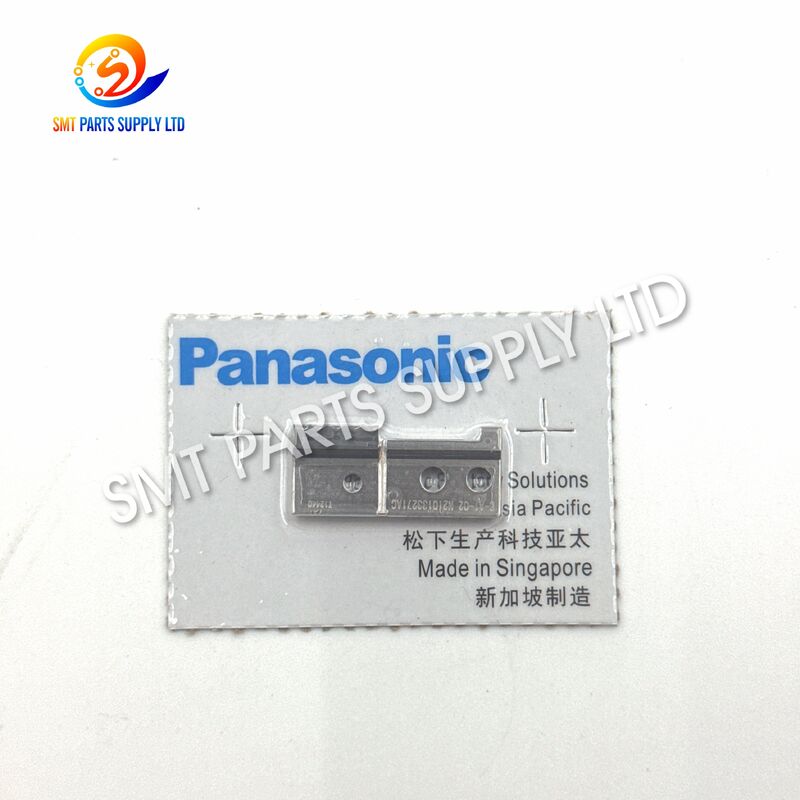
Created with Pixso. Panasonic N210133271AC Precision Metal Lead Cutter B for RG131 AI Machine with Stable and Repeatable Cutting

Panasonic N210133271AC Precision Metal Lead Cutter B for RG131 AI Machine with Stable and Repeatable Cutting

Brand Name: Panasonic
Model Number: N210133271AC
Detail Information
Place of Origin:
CHINA&JAPEN
Product Name:
Lead Cutter B
Brand:
Panasonic
Model Number:
N210133271AC
Part Number:
N210133271AC
Product Type:
AI Machine Cutter
Cutter Type:
Lead Cutter B
Compatible Machine:
RG131
Machine Category:
Automatic Insertion Machine
Application:
Through-Hole Component Lead Cutting
Main Function:
Trimming Excess Component Leads
Installation Area:
Lead Cutting Mechanism
Operating Method:
Repetitive Mechanical Cutting
Component Category:
Precision Mechanical Spare Part
Material:
Precision Metal
Manufacturing Method:
Precision Machining
Surface:
Machined Metal Surface
Feature:
Accurate Cutting Position
Performance:
Stable And Repeatable Cutting
Replacement Purpose:
Worn Or Damaged Cutter Replacement
Product Description
Panasonic N210133271AC Precision Lead Cutter B for RG131 AI Machine
Panasonic N210133271AC Precision Metal Lead Cutter B for RG131 AI Machine with Stable and Repeatable CuttingPanasonic N210133271AC Precision Metal Lead Cutter B for RG131 AI Machine with Stable and Repeatable CuttingPanasonic N210133271AC Precision Metal Lead Cutter B for RG131 AI Machine with Stable and Repeatable Cutting

The Panasonic N210133271AC Lead Cutter B is a precision mechanical replacement part used in the cutting section of compatible RG131 automatic insertion equipment. During component insertion production, the cutter helps trim component leads to the required length after positioning or insertion, supporting stable processing quality and repeatable machine operation.

As a frequently operated mechanical component, the cutter is exposed to repeated cutting loads, vibration, component lead contact, and gradual edge wear. A worn or damaged cutter may cause incomplete trimming, irregular lead length, excessive burrs, cutting resistance, or unexpected production interruptions. Timely replacement helps maintain cutting consistency and reduces the risk of downstream quality problems.

This product is suitable for electronics manufacturers, automatic insertion machine users, SMT and AI equipment service companies, spare-parts distributors, and maintenance departments. Customers should confirm part number N210133271AC, Cutter B orientation, machine model, installation dimensions, and old-part appearance before ordering.


Product Identification
Item Information
Brand Identification Panasonic
Part Number N210133271AC
Product Name Lead Cutter
Cutter Position Cutter B
Compatible Equipment RG131 automatic insertion machine
Product Category AI machine mechanical spare part
Main Function Cutting and trimming inserted component leads
Installation Type Machine-specific replacement component
Condition Options Original new, original used, or compatible new upon request
Ordering Requirement Confirm machine model, part number, orientation, and old-part photo

Why the Lead Cutter Is Important

Automatic insertion equipment must process a high number of through-hole components while maintaining stable lead length and consistent assembly quality. The lead cutting mechanism is therefore a critical part of the production cycle.

The N210133271AC Lead Cutter B works as part of the machine’s cutting system. Its operating condition can directly influence whether leads are trimmed cleanly, consistently, and at the correct position.

A cutter in good condition can help provide:

Production Requirement Operational Benefit
Clean cutting action Reduces rough or partially cut leads
Stable cutting position Supports consistent lead length
Smooth mechanical movement Reduces cutting resistance and vibration
Correct cutter alignment Helps prevent uneven contact
Repeatable operation Supports continuous production
Timely replacement Reduces unexpected machine downtime

Because the cutter repeatedly contacts metal component leads, it should be treated as a wear-sensitive production component. Its service life depends on production volume, component lead material, cutter alignment, lubrication condition, machine adjustment, and maintenance practices.


Cause: Common Reasons for Cutter Failure

Lead cutter problems normally develop gradually. Understanding the cause can help maintenance teams avoid replacing the cutter without correcting the underlying mechanical issue.

1. Normal Cutting Edge Wear

Repeated cutting cycles gradually reduce the sharpness of the cutting edge. Even when the cutter remains physically complete, its performance may decline after long-term production.

Typical results include:

  • Increased cutting resistance
  • Rough lead ends
  • Inconsistent cutting quality
  • Incomplete trimming
  • Higher mechanical load
  • More frequent production alarms
2. Incorrect Cutter Alignment

If Cutter A and Cutter B are not correctly aligned, the cutting surfaces may contact unevenly. Misalignment can cause localized wear, chipped edges, excessive friction, or deformation.

Alignment problems may result from:

  • Incorrect installation
  • Loose mounting hardware
  • Worn cutter holders
  • Damaged guide components
  • Mechanical impact
  • Previous maintenance errors
3. Hard or Oversized Component Leads

Component leads with unexpected hardness, diameter, shape, or material may create excessive cutting force. This condition can accelerate edge wear and increase the possibility of cutter damage.

Before changing component specifications, users should confirm that the lead dimensions are within the machine’s supported processing range.

4. Foreign Material in the Cutting Area

Lead fragments, dust, oil residue, packaging material, and other debris can enter the cutting mechanism. Contamination may interfere with cutter movement or prevent complete cutting contact.

Regular cleaning is especially important for high-volume automatic insertion lines.

5. Insufficient Maintenance

A cutter may fail early when the surrounding mechanism is not inspected regularly. Problems such as loose screws, worn guides, poor lubrication, incorrect clearance, or abnormal actuator movement can damage a newly installed cutter.

6. Mechanical Collision

A component positioning error, jammed lead, incorrect program setting, or unexpected obstruction may cause sudden impact. Even a small chip on the cutting edge can affect the quality of every subsequent cutting cycle.

7. Incorrect Part Selection

N210133271AC is identified as Cutter B. Installing the wrong cutter side, incorrect revision, or visually similar part may lead to installation difficulty or poor cutting performance.

Customers should not select a cutter only by general appearance.


Common Failure Symptoms
Symptom Possible Cause Recommended Check
Lead is not completely cut Worn cutting edge or insufficient stroke Inspect edge condition and cutter movement
Lead length is inconsistent Cutter movement or alignment problem Check guides, mounting position, and clearance
Lead end has excessive burrs Dull or damaged cutter edge Replace cutter and inspect matching cutting part
Machine produces abnormal noise Cutter interference or loose mounting Stop equipment and inspect installation
Cutter movement becomes slow Contamination, wear, or actuator issue Clean mechanism and inspect drive system
Cutter edge chips repeatedly Excessive load or incorrect alignment Check lead specification and cutting clearance
Frequent production stoppage Unstable cutter action Inspect the complete cutting assembly
New cutter wears quickly Related components are damaged Check holder, guide, actuator, and matching cutter
Lead fragments accumulate Poor cleaning or waste discharge Clean collection and discharge areas
Cutter cannot return smoothly Obstruction or mechanical resistance Inspect movement path and surrounding parts

Solution: Recommended Replacement and Maintenance Approach

Replacing the N210133271AC cutter is most effective when the complete cutting mechanism is inspected at the same time. Installing a new cutter without checking alignment, movement, and related wear may result in shortened service life.

Step 1: Confirm the Correct Part

Before ordering, verify:

  • Part number N210133271AC
  • Product description: Lead Cutter B
  • Equipment model: RG131
  • Cutter installation direction
  • Old-part shape and mounting points
  • Machine parts manual information
  • Revision suffix and machine configuration

Providing a clear old-part photograph is strongly recommended.

Step 2: Inspect the Matching Cutter

The cutting mechanism may use Cutter A and Cutter B as a coordinated cutting pair. When one side is heavily worn, the matching cutter should also be inspected.

Do not assume that replacing only one cutter will always restore proper cutting quality.

Step 3: Check the Cutter Holder and Guides

Inspect the mounting holder, guide surfaces, pins, screws, and movement path. Excessive play or deformation can prevent accurate cutter contact.

Step 4: Remove Lead Fragments and Contamination

Clean all metal fragments and process residue before installing the new part. The installation surface should be free from dust, burrs, and foreign material.

Step 5: Install Without Forcing the Component

The cutter should fit the correct mounting position without uncontrolled force. If installation resistance is abnormal, stop and reconfirm the part number, orientation, and mounting condition.

Step 6: Adjust Cutting Alignment

After installation, check cutter clearance, overlap, movement, and return action according to the equipment maintenance procedure.

Step 7: Test at Low Speed

Run the mechanism manually or at a reduced operating speed before restarting normal production. Observe the complete cutting cycle and confirm that there is no collision or abnormal sound.

Step 8: Inspect Sample Products

Check several processed components for:

  • Complete lead separation
  • Consistent lead length
  • Acceptable lead-end condition
  • No deformation around the insertion point
  • No abnormal PCB damage
  • No loose lead fragments
Step 9: Record the Replacement

Record the replacement date, machine number, production quantity, failure symptom, and maintenance result. This information helps establish a practical preventive-maintenance schedule.


Specifications
Specification Description
Product Name Lead Cutter B
Part Number N210133271AC
Brand Reference Panasonic
Machine Application RG131 automatic insertion equipment
Equipment Category AI through-hole component insertion machine
Spare-Part Category Precision mechanical cutting component
Primary Function Cutting and trimming component leads
Cutter Identification B-side cutter
Installation Position Lead cutting mechanism
Operation Type Repetitive mechanical cutting
Material Precision metal construction; exact alloy subject to production version
Surface Condition Machined cutting and mounting surfaces
Dimensional Standard Manufactured according to the corresponding part configuration
Replacement Type Direct machine-specific maintenance part after verification
Supply Status Subject to stock and selected condition
Minimum Order Quantity Available for sample or maintenance quantity
Packaging Protective individual packaging
Quality Inspection Appearance, part number, and dimensional checks before shipment
Shipping Method Express, air freight, or consolidated shipment
Compatibility Check Required before order confirmation
Warranty Subject to product condition and quotation terms

Key Product Features
Accurate Part Identification

The N210133271AC marking makes the cutter easier to identify during maintenance planning and spare-parts purchasing.

Designed for Cutter B Position

This component is specified as Lead Cutter B. Correct side identification helps prevent ordering errors involving the associated cutting components.

Precision Cutting Function

The cutter supports controlled component lead trimming during the automatic insertion process.

Stable Mechanical Operation

Correct installation and adjustment help provide repeatable cutter movement during continuous production.

Maintenance-Friendly Replacement

The component can be replaced during scheduled machine maintenance when the original cutter becomes worn, chipped, damaged, or unstable.

Suitable for Production Spare Stock

Factories operating RG131 equipment can keep this cutter as part of their critical spare-parts inventory to reduce downtime caused by unexpected cutter failure.

Individual Protective Packaging

Each cutter can be packed separately to reduce contact damage, moisture exposure, and cutting-edge impact during transportation.

Multiple Supply Conditions

Depending on customer requirements and availability, original new, original used, or compatible new options may be quoted separately. Product condition should always be stated clearly before purchase.


Application

The N210133271AC Lead Cutter B is primarily used in the lead cutting section of compatible RG131 automatic insertion equipment.

Typical Industries
Industry Application
Consumer Electronics Through-hole component assembly for electronic control products
Automotive Electronics Production of control boards and electrical modules
Power Supply Manufacturing Assembly of transformers, resistors, capacitors, and related components
Industrial Control PCB production for controllers and automation equipment
Home Appliances Assembly of appliance control boards
Lighting Electronics Production of LED power and control boards
Communication Equipment Through-hole PCB assembly
Electronics Contract Manufacturing High-volume customer PCB production
Equipment Maintenance Repair and servicing of automatic insertion machines
Spare-Parts Distribution Supply of AI machine replacement components
Typical Production Uses
  • Through-hole component insertion
  • Radial component processing
  • Component lead trimming
  • PCB assembly production
  • Automatic insertion line maintenance
  • Cutter mechanism repair
  • Preventive spare-parts replacement
  • Machine refurbishment
  • Production recovery after cutter damage
  • Critical maintenance stock preparation

Panasonic N210133271AC Precision Metal Lead Cutter B for RG131 AI Machine with Stable and Repeatable CuttingPanasonic N210133271AC Precision Metal Lead Cutter B for RG131 AI Machine with Stable and Repeatable CuttingPanasonic N210133271AC Precision Metal Lead Cutter B for RG131 AI Machine with Stable and Repeatable Cutting
How It Works

The cutter operates as part of the automatic insertion machine’s mechanical cutting system.

1. Component Feeding

The insertion equipment feeds the required component toward the processing position according to the production program.

2. Component Positioning

The machine positions and forms the component leads for insertion into the PCB holes.

3. PCB Insertion

The component leads enter the designated PCB holes while the component body remains correctly positioned.

4. Cutter Movement

The machine activates the cutting mechanism. Cutter A and Cutter B move into the required cutting relationship.

5. Lead Trimming

The cutting edges apply controlled mechanical force to separate the excess component lead material.

6. Cutter Return

After completing the cut, the mechanism returns to its starting position and prepares for the next production cycle.

7. Waste Collection

The trimmed lead material enters the designated waste or collection area. Regular cleaning is required to prevent fragments from interfering with the mechanism.

8. Cycle Repetition

The process repeats at production speed. Because the cutter may operate thousands of times during manufacturing, edge condition and alignment are essential for stable long-term performance.


Cutting Process Summary
Production Stage Cutter Involvement
Component preparation No cutting action
Lead positioning Cutter waits in home position
Component insertion Cutter prepares for activation
Cutting command Cutting mechanism moves
Lead separation Cutter trims excess lead
Mechanism return Cutter returns to home position
Product inspection Lead length and cutting quality are checked
Next component cycle Process repeats

Benefits of Timely Cutter Replacement
Improved Cutting Consistency

Replacing a worn cutter can help restore more uniform lead trimming and reduce variation between processed components.

Reduced Production Interruptions

A spare cutter kept in stock allows maintenance teams to respond more quickly when cutting problems occur.

Lower Risk of Secondary Damage

A damaged cutter can create abnormal load on holders, guides, actuators, and the matching cutter. Early replacement can reduce the possibility of additional mechanical damage.

Better Product Quality Control

Stable lead trimming supports consistent PCB appearance and downstream assembly requirements.

Easier Preventive Maintenance

Tracking cutter replacement frequency allows factories to estimate wear intervals and prepare spare parts before failure occurs.

Reduced Manual Rework

Clean and complete lead cutting can reduce the need for manual trimming or product correction after automatic insertion.


How to Choose the Correct Cutter

Selecting a cutter by appearance alone is not recommended. Similar components may have different mounting dimensions, cutter angles, orientations, or revision levels.

1. Confirm the Complete Part Number

The required number should be checked as:

N210133271AC

Do not ignore the final revision characters. Similar numbers may refer to another cutter, revision, or installation position.

2. Confirm Cutter A or Cutter B

This product is identified as Cutter B. If your old part is Cutter A, the required part number may be different.

3. Confirm the Machine Model

The main verified application is RG131 automatic insertion equipment. Machines with different configurations should be checked using the parts manual or old component.

4. Compare the Old Part

Provide photographs showing:

  • Front side
  • Back side
  • Cutting edge
  • Mounting holes
  • Side profile
  • Part-number marking
  • Installed position
5. Check the Machine Parts Manual

The machine parts book is the preferred source for confirming the correct part number and assembly position.

6. Confirm Product Condition

Ask the supplier to state whether the quotation is for:

Condition Description
Original New New part supplied under original-brand identification
Original Used Previously installed original part, inspected before shipment
Compatible New Newly manufactured compatible replacement
Refurbished Used component restored or serviced before supply

These conditions should not be treated as identical.

7. Confirm Quantity and Packaging

For urgent maintenance, one piece may be sufficient. For factories operating multiple RG131 machines, keeping additional units in inventory may reduce future downtime.

8. Request Inspection Information

Before shipment, customers may request:

  • Actual product photographs
  • Part-number confirmation
  • Dimensional comparison
  • Condition confirmation
  • Packaging photographs
  • Quantity confirmation
  • Visual inspection report

Buyer Verification Checklist
Verification Item Buyer Confirmation
Part number is N210133271AC Required
Product is Lead Cutter B Required
Machine is RG131 Required
Old part appearance matches Required
Mounting dimensions match Recommended
Cutter direction matches Required
Product condition is accepted Required
Quantity is confirmed Required
Delivery schedule is confirmed Required
Related cutter condition is checked Recommended

Installation Recommendations

Installation should be completed by trained maintenance personnel familiar with automatic insertion equipment.

Before Installation
  • Stop the machine completely.
  • Disconnect or isolate the required energy sources.
  • Follow factory lockout and safety procedures.
  • Remove loose component leads from the work area.
  • Prepare clean installation tools.
  • Compare the new and old cutter.
  • Check the matching cutter for wear.
  • Inspect mounting screws and guides.
During Installation
  • Keep the cutting edge protected.
  • Avoid dropping or striking the cutter.
  • Install the part in the correct direction.
  • Do not force misaligned mounting holes.
  • Tighten fasteners evenly.
  • Check free movement before automatic operation.
  • Adjust clearance according to the machine procedure.
After Installation
  • Operate the mechanism manually when possible.
  • Conduct a low-speed test.
  • Listen for abnormal mechanical noise.
  • Confirm smooth cutter return.
  • Inspect the first processed components.
  • Recheck mounting stability.
  • Record the replacement in the maintenance file.

Maintenance Guide
Maintenance Item Suggested Action
Cutting edge Inspect for wear, chips, deformation, and residue
Cutter alignment Check for even contact and correct clearance
Mounting screws Confirm that fasteners remain secure
Cutter holder Inspect for wear, movement, or deformation
Guide mechanism Check for smooth travel and excessive play
Lead fragments Remove from the cutting and waste areas
Lubrication points Maintain according to machine requirements
Actuator movement Confirm complete forward and return strokes
Sample products Inspect lead length and cutting quality
Maintenance record Record inspection and replacement dates

Maintenance frequency should be determined according to production volume, component type, machine condition, and internal quality requirements.


Storage and Handling

The cutting edge should be protected during storage and transportation.

Recommended Storage Conditions
  • Store in a clean and dry environment.
  • Keep the cutter inside protective packaging.
  • Prevent direct contact between cutting edges and hard objects.
  • Avoid high humidity and corrosive substances.
  • Use clear part-number labels.
  • Separate Cutter A and Cutter B inventory.
  • Follow first-in, first-out inventory control.
  • Do not stack heavy items on the package.
Handling Precautions
  • Wear suitable protective gloves.
  • Do not touch the cutting edge unnecessarily.
  • Do not use the cutter as a general hand tool.
  • Avoid impact, bending, grinding, or uncontrolled polishing.
  • Keep the component away from magnetic debris and metal fragments.

Quality Control Before Shipment

Each order can be checked according to the confirmed purchasing requirements.

Inspection Point Inspection Content
Part Number Confirm N210133271AC
Product Type Confirm Lead Cutter B
Quantity Match purchase order quantity
Appearance Check for visible damage, rust, or deformation
Cutting Edge Check for obvious chips or impact marks
Mounting Area Check holes and installation surfaces
Product Condition Confirm new, used, compatible, or refurbished status
Packaging Protect the cutter from impact and moisture
Labeling Show part number and quantity clearly
Customer Requirement Confirm requested photographs or documents

Packaging and Delivery

The cutter is a precision metal component and should be packed to avoid impact on the cutting edge.

Standard Packaging Process
  1. Clean visual inspection
  2. Cutting-edge protection
  3. Anti-moisture protective wrapping
  4. Individual plastic or foam packaging
  5. Part-number label application
  6. Reinforced inner carton placement
  7. Export carton packaging
  8. Final quantity verification
Available Shipping Methods
Shipping Method Suitable Situation
International Express Urgent maintenance orders and small quantities
Air Freight Medium-volume orders requiring faster delivery
Sea Freight Large consolidated spare-parts shipments
Customer Courier Account Buyers with DHL, FedEx, UPS, or other accounts
Combined Shipment Cutter shipped together with other machine parts

Delivery time depends on stock condition, order quantity, product condition, inspection requirements, and destination.


Why Purchase From a Professional AI Spare-Parts Supplier

A specialized supplier can provide more than a general product quotation.

Part-Number Verification

The supplier can compare the requested number with available product information and old-part photographs.

Actual Product Photos

Customers can request real photographs before shipment, especially when purchasing used or compatible parts.

Combined Spare-Parts Supply

The cutter can be supplied together with guides, plates, holders, cylinders, motors, sensors, cables, and other automatic insertion machine components.

Flexible Order Quantity

Small maintenance orders and larger spare-stock orders can be handled according to customer requirements.

International Shipping Experience

Parts can be packed for export and shipped to electronics factories, repair companies, and distributors worldwide.

After-Sales Communication

Clear product identification before shipment can reduce return risk and purchasing errors.


Frequently Asked Questions
Q1: What is the N210133271AC used for?

N210133271AC is a Lead Cutter B used in the cutting mechanism of compatible RG131 automatic insertion equipment. It trims excess component lead material during the through-hole component insertion process. The exact installation position should be verified using the machine parts manual and the removed cutter.

Q2: Is N210133271AC the same as N210133270AC?

No. The two numbers are commonly identified as different sides of the lead cutting arrangement. N210133270AC is generally identified as Cutter A, while N210133271AC is Cutter B. Customers should verify which side is required before placing an order.

Q3: Can this cutter be installed directly without adjustment?

Installation normally requires inspection and mechanical adjustment. The maintenance technician should check cutter orientation, mounting condition, alignment, clearance, movement, and the condition of the matching cutter. A low-speed test should be completed before normal production resumes.

Q4: How can I confirm compatibility before ordering?

Please provide the complete part number, machine model, machine serial information when available, and clear photographs of the old cutter. Photos of the front, back, side profile, cutting edge, mounting holes, and installed position are especially useful for comparison.

Q5: When should the cutter be replaced?

Replacement should be considered when the cutter produces incomplete cuts, irregular lead lengths, excessive burrs, abnormal noise, increased cutting resistance, visible edge wear, chipping, or repeated production alarms. The complete cutting mechanism should also be inspected before installing a new cutter.


Contact Us

Looking for Panasonic N210133271AC Lead Cutter B or other automatic insertion machine spare parts?

Please send us the following information for a fast and accurate quotation:

  • Required part number
  • Machine model
  • Required quantity
  • Preferred product condition
  • Old-part photographs
  • Delivery destination
  • Courier account, when applicable
  • Expected delivery schedule

We supply automatic insertion machine parts, SMT machine parts, feeders, nozzles, cutters, guides, sensors, motors, cylinders, control boards, cables, filters, and other electronics manufacturing equipment components.

Our sales team can assist with part-number checking, product photo confirmation, stock availability, combined shipment planning, and international delivery.

Send your inquiry today for product verification, current stock information, and a competitive quotation.