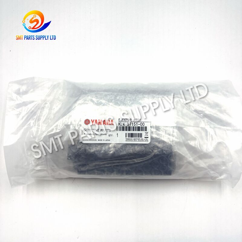
| Brand Name: | Yamaha |
| Model Number: | KLW-M7151-00 |
Yamaha KLW-M7151-00 ZZB10-X177 Solenoid Valve Inlet Fitting YSM10 YSM20 YSM20R
![]()
![]()
![]()
The Yamaha KLW-M7151-00 ZZB10-X177 solenoid valve air inlet fitting is a compact pneumatic connection component designed for compatible YSM-series SMT placement machines. It provides a stable connection between the compressed-air tube and the relevant solenoid valve, ejector, manifold, or vacuum-control assembly. A correctly matched fitting helps maintain secure tube retention, reliable airflow transfer, and consistent pneumatic response during high-speed component placement.
This component is suitable for YSM10, YSM20, and YSM20R machine maintenance, pneumatic-system repair, valve assembly servicing, and spare-parts inventory management. The combined KLW-M7151-00 and ZZB10-X177 references help purchasing and maintenance teams identify the required component more accurately. Because machine revisions and pneumatic configurations may differ, the complete part number, thread interface, tube diameter, installation direction, and removed-part appearance should be confirmed before ordering.
| Item | Details |
|---|---|
| Product Name | Solenoid Valve Air Inlet Fitting |
| Primary Part Number | KLW-M7151-00 |
| Component Model | ZZB10-X177 |
| Brand Reference | Yamaha |
| Equipment Type | SMT Pick-and-Place Machine |
| Compatible Models | YSM10, YSM20, YSM20R |
| Product Category | SMT Pneumatic Valve Component |
| Main Function | Connects compressed-air tubing to the valve inlet |
| Installation Area | Solenoid valve, ejector, manifold, or pneumatic control assembly |
| Working Medium | Clean and dry compressed air |
| Supply Scope | Fitting only unless otherwise confirmed |
| Verification Method | Part number, photograph, dimensions, thread, and tube size |
Although an air inlet fitting is a relatively small component, it plays an important role in the pneumatic system of an SMT placement machine. A damaged, loose, contaminated, or incorrectly selected fitting may cause unstable air delivery and affect the performance of the connected valve or vacuum circuit.
Air leakage may occur when the tube is not fully inserted, the fitting seal is worn, the thread is damaged, or the valve port is contaminated. Continuous leakage can reduce available air pressure and increase compressor workload.
Repeated tube installation and removal may gradually wear the internal tube-retention structure. A worn fitting may no longer hold the pneumatic tube securely during continuous machine operation.
Cross-threading, excessive tightening, incorrect tools, or installation at the wrong angle may damage the fitting thread or the connected valve port. A damaged thread can prevent correct sealing.
Dust, oil residue, moisture, sealing material, or other contamination may partially block the fitting passage. Restricted airflow may cause delayed pneumatic response or weak vacuum performance.
Maintenance tools or nearby moving components may accidentally strike the fitting. A cracked or deformed body should be replaced immediately to prevent sudden air leakage.
A tube that is too small may not seal correctly, while an oversized tube may damage the internal locking structure. Tube size should always be measured rather than estimated visually.
YSM-series machines may use different pneumatic configurations depending on production year, head specification, valve version, or machine revision. Similar-looking fittings are not automatically interchangeable.
| Failure Symptom | Possible Cause | Recommended Action |
|---|---|---|
| Audible air leakage | Loose tube or damaged seal | Reinsert the tube and inspect the fitting |
| Reduced vacuum performance | Restricted or insufficient airflow | Check fitting, valve, filter, tube, and ejector |
| Tube becomes loose | Worn locking mechanism | Replace the fitting and inspect the tube |
| Delayed valve response | Air restriction or unstable pressure | Check the complete pneumatic circuit |
| Fitting cannot be tightened | Damaged or incorrect thread | Compare with the removed component |
| Cracked fitting body | Excessive force or mechanical impact | Replace immediately |
| Repeated pickup errors | Unstable vacuum or valve operation | Inspect upstream and downstream components |
| Air pressure drops quickly | Leakage at fitting or connected assembly | Perform a controlled leakage test |
Replacing the worn or damaged KLW-M7151-00 ZZB10-X177 fitting with a correctly identified component helps restore a secure compressed-air connection. A proper replacement supports stable airflow, reliable valve switching, consistent vacuum generation, and reduced pneumatic leakage.
Correct selection should not depend only on the product photograph. The complete part number, body design, connection direction, tube outside diameter, thread specification, installation position, and surrounding valve assembly should be checked together.
| Step | Recommended Procedure |
|---|---|
| 1 | Stop the SMT machine according to the approved maintenance procedure |
| 2 | Shut off the compressed-air supply and release residual pressure |
| 3 | Photograph the original fitting and tube routing |
| 4 | Record the machine model and all visible markings |
| 5 | Remove the pneumatic tube carefully |
| 6 | Remove the old fitting using the correct tool |
| 7 | Inspect the valve port for damage or contamination |
| 8 | Compare the new fitting with the removed sample |
| 9 | Install the confirmed replacement component |
| 10 | Reconnect the correct tube completely |
| 11 | Restore air pressure gradually |
| 12 | Check for leakage and complete a functional machine test |
| Benefit | Production Value |
|---|---|
| Secure Pneumatic Connection | Helps prevent tube movement and accidental disconnection |
| Stable Airflow | Supports repeatable operation of the connected valve circuit |
| Reduced Leakage | Helps maintain pneumatic-system efficiency |
| Reliable Vacuum Response | Supports stable component pickup and release |
| Faster Maintenance | Clearly identified spare parts reduce repair time |
| Lower Purchasing Risk | Interface verification helps prevent incorrect orders |
| Improved Inventory Control | Part-number records simplify spare-parts management |
| Reduced Downtime | Prepared replacement stock supports fast recovery |
| Specification | Description |
|---|---|
| Product Name | Solenoid Valve Air Inlet Fitting |
| Primary Part Number | KLW-M7151-00 |
| Component Model | ZZB10-X177 |
| Equipment Application | SMT Surface-Mounting Machine |
| Compatible Machine References | YSM10, YSM20, YSM20R |
| System Type | Pneumatic and Vacuum-Control System |
| Main Function | Transfers compressed air into the relevant valve assembly |
| Installation Type | Pneumatic tube and threaded port connection |
| Connection Direction | Confirm against the removed component |
| Tube Diameter | Confirm before ordering |
| Port Thread | Confirm using the original fitting or valve body |
| Body Configuration | Compact pneumatic fitting |
| Working Medium | Filtered, clean, dry compressed air |
| Operating Pressure | Follow the machine pneumatic specification |
| Operating Temperature | Follow the equipment operating environment |
| Material | According to the confirmed supplied version |
| Product Condition | New original or compatible supply according to quotation |
| Installation Position | Valve, ejector, manifold, or related pneumatic assembly |
| Inspection | Part number, appearance, interface, and thread checking |
| Packaging | Individual protective export packaging |
| Minimum Order Quantity | Negotiable |
| Lead Time | Subject to stock and order quantity |
| Export Supply | Available for international industrial customers |
Exact tube size, thread standard, body material, internal sealing structure, and applicable machine revision should be confirmed before purchase. Visually similar pneumatic fittings may have different interfaces and should not be selected only by appearance.
The following components may be installed in the same pneumatic system, but they perform different functions and are not automatically interchangeable.
| Reference | Component Type | Main Function | Selection Basis |
|---|---|---|---|
| KLW-M7151-00 / ZZB10-X177 | Air inlet fitting | Connects incoming pneumatic tubing | Part number, tube size, thread, and body shape |
| KLW-M7151-Series Variant | Related pneumatic component | Depends on machine configuration | Complete suffix and machine BOM |
| KLW-M7154-00 | Related vacuum-generation component | Supports the vacuum-control circuit | Assembly model and installation position |
| KLW-M7157-00 | Related ejector or valve component | Controls or supports pneumatic ejection | Full part number and valve configuration |
| Complete Solenoid Valve | Pneumatic control valve | Switches compressed-air flow | Voltage, port design, connector, and model |
| Pneumatic Tube | Air supply line | Transfers compressed air | Outer diameter, material, and routing |
| Exhaust Muffler | Valve exhaust component | Reduces exhaust noise and contamination | Port size and airflow requirement |
| Valve Manifold | Multi-valve mounting assembly | Distributes air between valve circuits | Machine model and complete assembly number |
| Verification Item | Required Information |
|---|---|
| Machine Model | YSM10, YSM20, YSM20R, or exact alternative |
| Complete Part Number | KLW-M7151-00 or the full installed suffix |
| Component Marking | ZZB10-X177 or another visible reference |
| Tube Diameter | Accurate outside diameter measurement |
| Thread Interface | Compare with the original fitting |
| Body Direction | Straight, angled, or another configuration |
| Installation Location | Valve inlet, manifold, ejector, or head assembly |
| Machine Revision | Serial number or BOM information when available |
| Required Quantity | Emergency replacement or maintenance stock |
| Supply Scope | Fitting only or complete valve assembly |
The KLW-M7151-00 ZZB10-X177 fitting can be used during scheduled maintenance of compatible YSM-series SMT machines. It is suitable for replacing fittings that show leakage, mechanical damage, weak tube retention, or thread wear.
When the solenoid valve remains functional but the inlet fitting is damaged, replacing only the confirmed fitting may restore the pneumatic connection without replacing the complete valve assembly.
SMT placement machines use pneumatic and vacuum circuits to pick, hold, place, and release electronic components. Stable airflow entering the valve or ejector assembly helps maintain reliable vacuum-system operation.
Used YSM10, YSM20, and YSM20R machines may require replacement of aged pneumatic fittings before being returned to production. Inspection of valves, tubes, fittings, filters, and ejectors is recommended during refurbishment.
Keeping a verified fitting in local inventory can shorten machine downtime when the original component is damaged during production or maintenance.
Electronics manufacturers and SMT service companies can stock this fitting according to installed machine quantity, maintenance history, production schedule, and international delivery time.
| Customer Type | Typical Requirement |
|---|---|
| EMS Factory | Reliable replacement for production maintenance |
| PCB Assembly Plant | Preventive pneumatic spare parts |
| SMT Equipment Distributor | Clear part-number identification |
| Machine Refurbishment Company | Replacement of worn pneumatic components |
| Technical Service Provider | Accurate component matching |
| Multinational Electronics Factory | Standardized maintenance inventory |
| Used Equipment Supplier | Machine inspection and preparation |
| Industrial Maintenance Department | Fast repair and reduced downtime |
| Application Scenario | Product Purpose |
|---|---|
| Air leakage repair | Restores the inlet connection |
| Valve assembly servicing | Replaces a damaged pneumatic fitting |
| Vacuum-performance inspection | Eliminates a possible airflow leakage point |
| Machine overhaul | Replaces aged or contaminated fittings |
| Spare-parts preparation | Supports emergency maintenance |
| Tube replacement | Ensures correct tube-to-valve connection |
| Production-line relocation | Replaces fittings damaged during machine movement |
| Preventive maintenance | Reduces unexpected pneumatic failures |
The fitting provides the mechanical and pneumatic connection between the compressed-air tube and the relevant valve or vacuum-control assembly.
Clean and dry compressed air is supplied through the machine’s pneumatic distribution system.
The pneumatic tube is inserted into the fitting according to the required tube diameter and connection method. The internal retention structure helps hold the tube securely.
The fitting creates a sealed path between the tube and valve inlet. Proper installation helps reduce unwanted air loss.
Compressed air travels through the internal passage and enters the connected solenoid valve, manifold, ejector, or vacuum generator.
The machine control system activates the related valve. The valve then directs, stops, or releases compressed air according to the placement cycle.
The downstream circuit may generate vacuum, control air release, support component pickup, or perform another pneumatic function.
| Operating Stage | Function of the Fitting |
|---|---|
| Air Supply | Receives compressed air from the tube |
| Tube Retention | Holds the pneumatic tube in position |
| Sealing | Helps prevent leakage around the connection |
| Air Transfer | Directs air into the valve assembly |
| Valve Switching | Supports stable downstream pneumatic response |
| Production Cycle | Repeats airflow delivery during machine operation |
A small pneumatic leakage point may influence several machine functions. Reduced airflow can lead to slow valve response, weak vacuum generation, unstable pickup performance, component-release problems, or repeated machine alarms.
The fitting should therefore be inspected together with the complete pneumatic circuit, including the tube, filter, pressure regulator, valve, ejector, manifold, muffler, vacuum sensor, and sealing components.
Use the complete KLW-M7151-00 reference. Do not select the product only by the partial number KLW-M7151 because different suffixes may indicate different configurations.
Check whether ZZB10-X177 appears on the removed fitting, original packaging, machine BOM, maintenance record, or component label.
State whether the machine is YSM10, YSM20, YSM20R, or another model. Machine-series information alone may not be sufficient.
Use an accurate measuring tool to confirm the tube size. An incorrect tube diameter may cause leakage or damage the fitting.
The thread must match the valve port. Incorrect threads may damage the valve body, prevent correct tightening, or create air leakage.
Confirm whether the original fitting is straight, angled, compact, extended, or equipped with any special airflow-control structure.
The replacement fitting should provide sufficient clearance for the tube and surrounding machine components.
Before purchasing, specify whether the order requires:
For accurate confirmation, provide:
State whether the order requires an original component, compatible replacement, new unit, or another condition. Final supply conditions should be written clearly in the quotation.
| Information | Requirement |
|---|---|
| Complete Machine Model | Required |
| Full Part Number | Required |
| Component Marking | Required |
| Required Quantity | Required |
| Removed-Part Photograph | Strongly Recommended |
| Installation Photograph | Recommended |
| Tube Outside Diameter | Required when uncertain |
| Thread Measurement | Required when uncertain |
| Product Condition | Required |
| Delivery Country | Required |
| Shipping Method | Recommended |
| Required Delivery Date | Recommended |
Installation should be performed by trained maintenance personnel familiar with SMT placement equipment and pneumatic systems.
| Installation Risk | Prevention Method |
|---|---|
| Cross-threading | Begin installation manually before tightening |
| Valve-port damage | Use the correct tool and controlled force |
| Air leakage | Confirm tube size and full insertion |
| Tube restriction | Avoid sharp bends and excessive tension |
| Internal contamination | Keep the fitting and valve port clean |
| Wrong component | Compare all interfaces before installation |
| Residual-pressure injury | Release compressed air before removal |
| Production malfunction | Complete a functional test before normal production |
The KLW-M7151-00 and ZZB10-X177 references can be checked against the customer’s purchase order and confirmation information.
The fitting body should be checked for cracks, deformation, corrosion, contamination, impact marks, or other visible damage.
The thread should be clean and free from obvious damage that may prevent correct installation.
The tube interface and release mechanism can be inspected for visible damage, contamination, or deformation.
When the customer provides clear photographs or a physical sample, the replacement can be compared for body shape, marking, connection direction, and overall interface.
Each fitting should be protected against dust, moisture, impact, and movement during international transportation.
| Inspection Item | Inspection Purpose |
|---|---|
| Part Number | Confirms ordered reference |
| Model Marking | Verifies ZZB10-X177 identification |
| Body Condition | Detects cracks or deformation |
| Thread Condition | Reduces installation risk |
| Tube Interface | Checks connection condition |
| Sealing Area | Helps prevent leakage |
| Product Quantity | Confirms order amount |
| Packaging | Protects the fitting during transportation |
| Label Information | Reduces dispatch errors |
| Customer Photo Comparison | Supports compatibility confirmation |
Moisture, oil, and dust can affect fittings, valves, seals, filters, and ejectors. Follow the machine manufacturer’s pneumatic maintenance requirements.
A damaged, hardened, scratched, flattened, or incorrectly cut tube may continue leaking even after the fitting is replaced.
When vacuum performance remains unstable, inspect the upstream and downstream system rather than replacing only one component.
Frequent tube removal can accelerate wear of the tube end and retention mechanism.
Factories operating multiple YSM machines should keep a reasonable quantity of confirmed fittings for emergency maintenance.
| Record Item | Information |
|---|---|
| Machine Model | YSM10, YSM20, or YSM20R |
| Machine Identification | Factory equipment number |
| Replacement Date | Maintenance completion date |
| Removed Part Number | Complete visible reference |
| Installed Part Number | KLW-M7151-00 / ZZB10-X177 |
| Failure Symptom | Leakage, damage, or weak tube retention |
| Related Parts Checked | Tube, valve, ejector, filter, and manifold |
| Test Result | Leakage and functional test results |
| Technician | Maintenance employee |
| Next Inspection | Planned maintenance date |
No. This listing mainly describes the pneumatic air inlet fitting. The solenoid valve, ejector, manifold, pneumatic tube, and mounting accessories are included only when clearly stated in the quotation.
It is referenced for compatible YSM-series applications, but machine revisions may use different valve or fitting configurations. Confirm the complete part number, tube size, thread, and removed-part photograph before ordering.
A similar appearance does not guarantee compatibility. Different fittings may use different threads, tube diameters, airflow passages, sealing structures, body lengths, or installation directions.
Please provide the machine model, complete part number, required quantity, removed-part photographs, tube diameter, thread details, product condition, delivery country, and expected delivery date.
Inspect the pneumatic tube, tube cut surface, fitting thread, valve port, sealing method, manifold, valve body, ejector, filter, regulator, and nearby connections. The leakage may come from another component.
Please send the following information for a fast and accurate quotation:
Our sales team can provide product identification support, availability confirmation, quotation details, packaging information, estimated preparation time, shipping options, and combined SMT spare-parts supply.
For faster processing, include KLW-M7151-00 ZZB10-X177 in the inquiry subject and attach clear photographs of the removed fitting and installation position.
Yamaha and the referenced machine model names are used only to identify product compatibility and application. All trademarks belong to their respective owners. Product origin, condition, manufacturer, and supply status should be confirmed in the final commercial quotation.