logo
Good price  online

products details

Created with Pixso. Home Created with Pixso. Products Created with Pixso.
SMT Nozzle
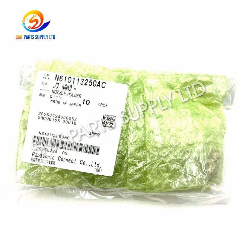
Created with Pixso. Panasonic N610113250AC Sintered Nozzle Holder for CM402 8-Head SMT Placement

Panasonic N610113250AC Sintered Nozzle Holder for CM402 8-Head SMT Placement

Brand Name: Panasonic
Model Number: N610113250AC
Detail Information
Place of Origin:
CHINA&JAPEN
Brand:
Panasonic
Product Name:
Sintered Nozzle Holder
Part Number:
N610113250AC
Standard Description:
Nozzle Holder, Sintered
Part Family:
N610113250 Series
Product Category:
SMT Placement-Head Spare Part
Machine Category:
SMT Pick-and-Place Machine
Common Machine Model:
CM402
Common Head Configuration:
8-Head Configuration
Primary Function:
Supports And Positions The Placement Nozzle
Secondary Function:
Guides Repeated Nozzle Movement
Installation Position:
Placement-Head Nozzle Mechanism
Material Structure:
Sintered Mechanical Construction
Application:
Electronic Component Pickup And Placement
Suitable Use:
Maintenance, Repair, And Head Refurbishment
Applicable Industry:
Electronics Manufacturing
Suitable Production Line:
Automated PCB Assembly Line
Condition Options:
Original New Or Compatible New
Unit:
Piece
Highlight:

Panasonic CM402 SMT nozzle holder

,

Sintered SMT nozzle holder

,

8-head SMT placement nozzle

Product Description

Panasonic N610113250AC Sintered Nozzle Holder for CM402 8-Head SMT

Panasonic N610113250AC Sintered Nozzle Holder for CM402 8-Head SMT PlacementPanasonic N610113250AC Sintered Nozzle Holder for CM402 8-Head SMT PlacementPanasonic N610113250AC Sintered Nozzle Holder for CM402 8-Head SMT Placement

The Panasonic N610113250AC is a precision sintered nozzle holder designed for use within compatible SMT placement-head mechanisms. It supports the installation, positioning, guidance, and repeated movement of the placement nozzle during automated component pickup and placement operations.

This component is commonly referenced for CM402 8-head SMT placement applications. During production, the nozzle holder works continuously as the machine picks components from feeders, transports them through the vision-recognition process, and places them accurately onto printed circuit boards.

A correctly matched nozzle holder helps maintain stable nozzle seating, smooth vertical travel, reliable vacuum pickup, and consistent placement performance. N610113250AC is suitable for preventive maintenance, placement-head refurbishment, emergency machine repair, and critical spare-parts inventory.

Because machines may have different head configurations and engineering revisions, buyers should confirm the complete part number, suffix, machine model, head type, and existing component before placing an order.

Product Identification
Item Product Information
Brand Panasonic
Main Part Number N610113250AC
Standard Product Name Nozzle Holder, Sintered
Product Type SMT Placement-Head Mechanical Component
Common Machine Reference CM402
Common Head Reference 8-Head Placement Configuration
Product Category SMT Pick-and-Place Machine Spare Part
Primary Function Supports, positions, and guides the placement nozzle
Installation Area Placement-head nozzle mechanism
Typical Use Maintenance, repair, refurbishment, and replacement
Condition Options Original New or Compatible New
Sales Unit Piece
What Is the N610113250AC Nozzle Holder?

The N610113250AC is a mechanical support component installed inside a compatible SMT placement head. Its primary purpose is to hold and guide the nozzle used to pick electronic components from feeders and place them onto PCB pads.

Although the nozzle holder is relatively small, it participates in every component-placement cycle. A production machine may complete thousands of repeated movements per hour, making stability, dimensional accuracy, smooth operation, and correct installation especially important.

The holder must work together with the nozzle, shaft, spring, seal, vacuum circuit, placement head, sensors, and control system. Wear or damage in any connected component may affect pickup and placement performance.

Main Product Functions
Function Description
Nozzle Support Provides a stable installation position for the placement nozzle
Positioning Control Helps keep the nozzle correctly aligned inside the head mechanism
Vertical Guidance Supports controlled upward and downward nozzle movement
Motion Transmission Transfers mechanical movement from the placement head to the nozzle
Vacuum Pickup Support Helps maintain correct nozzle seating during vacuum pickup
Placement Stability Supports consistent component pickup and placement cycles
Maintenance Replacement Allows worn or damaged holder components to be replaced
Head Refurbishment Used during inspection and rebuilding of placement-head assemblies
Why Nozzle-Holder Condition Is Important

The placement nozzle directly contacts or lifts electronic components, but its performance also depends on the holder supporting it.

A properly selected and installed holder can help provide:

  • Stable nozzle installation.
  • Smooth vertical movement.
  • Accurate nozzle positioning.
  • Repeatable component pickup.
  • Consistent component presentation to the vision camera.
  • Reliable nozzle return movement.
  • Reduced mechanical play.
  • Stable operation during high-speed production.
  • Easier placement-head calibration.
  • Lower risk of repeated pickup faults.

An incorrect or worn holder may cause inconsistent movement, excessive clearance, nozzle offset, abnormal pickup height, or irregular vacuum performance.

Two nozzle holders may look similar while having different internal structures, dimensional tolerances, installation interfaces, or revision suffixes. The complete part number should therefore be checked before ordering.

Cause: Why a Nozzle Holder Requires Replacement
1. Long-Term Mechanical Wear

The holder operates repeatedly during every pickup and placement cycle. Over time, contact surfaces, guiding areas, and internal interfaces may become worn.

Typical results include:

  • Increased mechanical clearance.
  • Unstable nozzle positioning.
  • Irregular vertical movement.
  • Reduced placement repeatability.
  • Abnormal nozzle vibration.
2. Dust and Production Contamination

SMT production environments may contain component dust, PCB particles, oil mist, solder-paste residue, adhesive material, and other contaminants.

Contamination may cause:

  • Restricted holder movement.
  • Increased internal friction.
  • Vacuum-passage blockage.
  • Poor nozzle seating.
  • Irregular return action.
3. Nozzle Collision

The nozzle may collide with:

  • Incorrectly positioned feeders.
  • Raised PCB components.
  • Board fixtures.
  • Tray edges.
  • Misaligned components.
  • Incorrectly programmed placement coordinates.

Impact force may pass through the nozzle and damage or deform the holder.

4. Incorrect Nozzle Installation

Installing an unsuitable nozzle, forcing the nozzle into position, or failing to seat it correctly may place abnormal stress on the holder.

5. Improper Maintenance

The holder may be damaged by:

  • Unsuitable removal tools.
  • Excessive installation force.
  • Incorrect cleaning chemicals.
  • Unapproved lubricants.
  • Improper disassembly.
  • Contamination during servicing.
6. Revision Mismatch

Using a similar-looking holder with the wrong suffix may cause poor fit, restricted movement, incorrect nozzle height, vacuum leakage, or calibration problems.

7. Placement-Head Refurbishment

During a complete head-rebuilding project, the holder may be replaced together with springs, seals, shafts, bushings, filters, and other wear components.

Common Failure Symptoms
Machine Symptom Possible Holder-Related Cause
Frequent Pickup Errors Nozzle alignment or holder movement may be unstable
Component Dropping Nozzle seating or vacuum transfer may be affected
Abnormal Nozzle Height Holder installation or mechanical travel may be incorrect
Repeated Placement Offset Mechanical play or alignment variation may exist
Nozzle Movement Is Not Smooth Contamination, deformation, or wear may be present
Nozzle Does Not Return Normally Internal resistance or connected spring wear may exist
Vision Recognition Errors Component position may be inconsistent during inspection
Abnormal Mechanical Noise Holder contact or movement may be restricted
One Head Position Performs Poorly A single holder position may be damaged or worn
Calibration Failure Incorrect revision, installation, or mechanical condition may exist

These symptoms can also be caused by nozzles, vacuum valves, filters, seals, sensors, springs, shafts, feeders, calibration data, or machine programming. A complete diagnosis should be performed before replacing parts.

Solution: Recommended Replacement Process
Step 1: Record the Complete Part Number

Check the installed holder and record the complete number, including the AC suffix. Do not identify the component only by appearance.

Step 2: Confirm the Machine Configuration

Provide the following information:

  • Machine model.
  • Machine serial number.
  • Placement-head model.
  • Number of head positions.
  • Existing holder marking.
  • Head assembly number.
Step 3: Photograph the Existing Component

Clear photographs should show:

  • Front view.
  • Rear view.
  • Side profile.
  • Mounting interface.
  • Internal opening.
  • Visible part-number marking.
  • Installation position in the head.
Step 4: Compare Important Interfaces

Compare the original and replacement holders for:

  • Overall dimensions.
  • Mounting points.
  • Nozzle connection.
  • Guide surfaces.
  • Spring interface.
  • Air or vacuum passages.
  • Internal diameter.
  • External profile.
  • Revision suffix.
Step 5: Inspect Related Head Components

Inspect the following parts before installation:

  • Placement nozzle.
  • Holder shaft.
  • Spring.
  • Seal.
  • Bushing.
  • Filter.
  • Vacuum valve.
  • Head sensor.
  • Nozzle-changing interface.

Replacing only the holder may not solve a fault caused by another damaged component.

Step 6: Install with Suitable Tools

Installation should be completed by trained technicians using clean tools and approved maintenance procedures.

Step 7: Test and Calibrate the Head

After installation, complete:

  • Manual movement inspection.
  • Nozzle installation test.
  • Vacuum test.
  • Nozzle-height inspection.
  • Head calibration.
  • Pickup verification.
  • Placement accuracy test.
  • Controlled production trial.
Specifications
Specification Details
Brand Panasonic
Product Model N610113250AC
Standard Description Nozzle Holder, Sintered
Part Family N610113250 Series
Product Category SMT Placement-Head Spare Part
Machine Type High-Speed SMT Pick-and-Place Machine
Common Machine Application CM402
Common Head Configuration 8-Head Configuration
Installation Position Nozzle Support Mechanism
Main Function Nozzle support, alignment, guidance, and movement
Construction Type Sintered Mechanical Holder
Operating Method Repeated mechanical movement during SMT placement
Application Environment Automated PCB Assembly Line
Suitable Industries EMS, electronics manufacturing, PCB assembly
Maintenance Use Preventive maintenance and emergency repair
Condition Options Original New or Compatible New
Order Quantity Available according to customer requirements
Unit Piece
Inspection Part number, appearance, interface, and condition
Packaging Individual protective packaging
Shipping International express, air freight, or consolidated shipment
Compatibility Requirement Confirm complete suffix and machine configuration
Warranty According to supplied condition and quotation terms
N610113250 Series Comparison
Part Number Product Reference Application Reference Selection Notice
N610113250AA Earlier nozzle-holder revision Common CM402 holder reference Confirm the machine BOM before ordering
N610113250AB Revised nozzle-holder model Commonly referenced for CM402 8-head use Compare the interface with the installed holder
N610113250AC Sintered nozzle holder Requested CM402 8-head maintenance part Match AC when the BOM or installed part specifies AC
N610071723AA Related holder reference Referenced in some CM402 holder assemblies Do not assume direct interchangeability
KXFX034YA04 Legacy holder reference Used in certain CM402 configurations Confirm dimensions and head assembly
N610009409AA Related holder model Used in selected placement-head assemblies Match by complete machine documentation
Revision Notice

AA, AB, and AC suffixes may represent design, process, material, supplier, or dimensional revisions.

For accurate ordering:

  • Match the complete part number.
  • Do not remove the suffix from the inquiry.
  • Do not assume all revisions are interchangeable.
  • Confirm the machine BOM whenever possible.
  • Compare the existing part before installation.
  • Request technical confirmation for modified or rebuilt machines.
Application

The N610113250AC nozzle holder is suitable for the following applications.

SMT Production-Line Maintenance

Used to replace a worn or damaged holder during scheduled equipment servicing.

Emergency Machine Repair

Maintained as a critical spare part to reduce downtime after a placement-head failure.

Placement-Head Refurbishment

Installed during professional rebuilding of older or heavily used head assemblies.

EMS Manufacturing

Suitable for electronics manufacturing service factories operating high-volume PCB assembly lines.

PCB Assembly Plants

Applicable to manufacturers producing:

  • Automotive electronics.
  • Industrial control boards.
  • Communication equipment.
  • Consumer electronics.
  • LED lighting products.
  • Medical electronic devices.
  • Power-supply assemblies.
  • Smart-home products.
SMT Service Companies

Used by service engineers for machine diagnosis, maintenance, refurbishment, and customer-site repair.

Used Equipment Rebuilding

Suitable for used SMT machine inspection and reconditioning before calibration, production testing, or resale.

Spare-Parts Distribution

Regional distributors may stock N610113250AC for local SMT customers requiring fast replacement service.

Application Scenario Table
Scenario Customer Requirement Product Function
Emergency Breakdown Restore production quickly Replaces a confirmed damaged holder
Preventive Maintenance Replace known wear parts Reduces unexpected head failure
Head Refurbishment Rebuild a used placement head Restores the nozzle-support mechanism
Spare Inventory Prepare critical components Reduces future procurement delays
Machine Relocation Inspect before restarting Replaces damage found during relocation
Quality Improvement Investigate pickup instability Corrects holder-related alignment problems
Used Machine Rebuilding Improve mechanical condition Supports calibration and production testing
Multi-Line Maintenance Standardize spare-parts control Allows inventory management by exact part number
Panasonic N610113250AC Sintered Nozzle Holder for CM402 8-Head SMT PlacementPanasonic N610113250AC Sintered Nozzle Holder for CM402 8-Head SMT PlacementPanasonic N610113250AC Sintered Nozzle Holder for CM402 8-Head SMT Placement
How It Works
1. Nozzle Installation

The placement nozzle is installed into or supported by the nozzle-holder mechanism. The holder maintains the required nozzle position inside the placement head.

2. Head Movement to the Feeder

The placement head moves rapidly toward the feeder pickup location. The holder supports nozzle stability during acceleration and deceleration.

3. Vertical Pickup Movement

The nozzle moves downward toward the electronic component. The holder guides this motion and helps maintain correct positioning.

4. Vacuum Pickup

The machine activates the vacuum system. Air is drawn through the nozzle, allowing the component to be lifted from the feeder.

5. Component Transportation

The placement head carries the component from the feeder to the vision camera or directly toward the PCB placement area.

6. Vision Recognition

The camera checks the component’s position, angle, shape, and orientation. Stable nozzle support helps provide repeatable component presentation.

7. Component Placement

The head moves to the programmed PCB coordinate. The nozzle travels downward and places the component onto solder paste or adhesive.

8. Vacuum Release

Vacuum is released, allowing the component to remain on the PCB.

9. Nozzle Return

The nozzle returns to its initial position, and the machine begins the next placement cycle.

Placement-Cycle Requirements
Placement Stage Holder Performance Requirement
Movement to Feeder Stable positioning during rapid head motion
Nozzle Lowering Smooth and controlled vertical travel
Component Pickup Correct nozzle seating and alignment
Vacuum Holding Stable connection within the pickup mechanism
Vision Inspection Repeatable component position
Movement to PCB Reliable support during transportation
Component Placement Controlled contact and accurate height
Nozzle Return Smooth return without sticking
Continuous Production Consistent performance over repeated cycles
How to Choose the Correct Nozzle Holder
1. Match N610113250AC Exactly

The safest selection method is to use the complete N610113250AC part number.

Do not submit the inquiry only as:

  • N610113250.
  • CM402 holder.
  • Panasonic nozzle holder.
  • Eight-head holder.

These descriptions may not identify the required revision accurately.

2. Confirm the Placement-Head Configuration

The same machine platform may use different head assemblies. State whether the application is an 8-head configuration and provide the head label when available.

3. Check the Existing Holder

Compare the replacement with the removed component before installation.

4. Confirm the Required Condition

Available supply options may include:

Condition Recommended Application
Original New High-value production lines requiring original supply
Compatible New Cost-controlled maintenance after technical confirmation
Inspected Used Temporary repair or discontinued-part requirements
Refurbished Assembly Complete placement-head repair projects
5. Provide Photographs

Photographs help identify:

  • Product shape.
  • Mounting interface.
  • Visible markings.
  • Revision differences.
  • Damage location.
  • Related components.
6. Confirm the Required Quantity

For emergency maintenance, purchasing one working unit and one backup unit can reduce future downtime.

Factories operating several compatible machines may prepare stock according to historical usage and maintenance schedules.

7. Check the Machine BOM

The machine bill of materials, maintenance manual, or head assembly drawing should be treated as the primary compatibility reference.

Buyer Inquiry Checklist
Required Information Customer Details
Required Part Number N610113250AC
Product Name Sintered Nozzle Holder
Machine Model CM402
Head Configuration 8-Head
Required Quantity Please specify
Required Condition Original New or Compatible New
Existing Holder Suffix AA, AB, or AC
Machine Serial Number Recommended when available
Destination Country Please specify
Required Delivery Time Please specify
Existing-Part Photos Strongly recommended
Courier Account DHL, FedEx, UPS, or supplier arrangement

Providing complete information helps reduce quotation delays and incorrect part selection.

Quality Inspection
Part-Number Inspection

The complete N610113250AC identification should be checked against the customer’s purchase request.

Appearance Inspection

The holder should be checked for:

  • Cracks.
  • Corrosion.
  • Deformation.
  • Impact damage.
  • Surface contamination.
  • Abnormal scratches.
  • Damaged interfaces.
Interface Inspection

Mounting areas, nozzle-contact surfaces, guide areas, and visible air passages should be inspected.

Movement Inspection

Where the structure allows, the holder should be checked for abnormal resistance, seizure, excessive looseness, or irregular movement.

Packaging Inspection

The holder should be individually protected from dust, moisture, impact, and contact with heavier metal parts.

Photographic Confirmation

Photographs may be supplied before shipment when customers require part-number, condition, or appearance confirmation.

Installation Recommendations

Installation should be performed by qualified SMT maintenance technicians.

  1. Stop the equipment according to the approved procedure.
  2. Isolate electrical power, compressed air, and vacuum where required.
  3. Remove the placement-head cover according to the maintenance manual.
  4. Record the original holder position and orientation.
  5. Remove the old component using suitable tools.
  6. Inspect the nozzle, shaft, spring, seal, bushing, and nearby parts.
  7. Clean the installation area carefully.
  8. Install N610113250AC without excessive force.
  9. Confirm that the mechanism moves freely.
  10. Restore the machine systems.
  11. Perform head calibration.
  12. Complete pickup and placement testing.
  13. Run a controlled production trial.

Do not grind, drill, bend, or modify the holder to fit an incompatible assembly.

Post-Installation Inspection
Inspection Item Acceptance Requirement
Mounting Holder is installed securely
Movement No sticking or excessive mechanical resistance
Nozzle Fit Nozzle installs and releases correctly
Nozzle Position No visible abnormal offset
Vacuum Response Stable vacuum pickup performance
Nozzle Height Meets the machine maintenance requirement
Head Calibration Calibration is completed successfully
Pickup Test Components are picked consistently
Placement Test Placement remains stable and repeatable
Production Trial No repeated holder-related faults appear
Maintenance Recommendations
  • Inspect the nozzle-holder mechanism during scheduled head maintenance.
  • Keep the placement-head area clean.
  • Replace damaged nozzles promptly.
  • Avoid using unapproved cleaning chemicals.
  • Do not apply excessive lubricant.
  • Inspect related seals, springs, shafts, and filters.
  • Store replacement holders in individual packages.
  • Label all inventory with the complete suffix.
  • Keep original and compatible parts separated.
  • Record the installation date and maintenance history.
  • Investigate repeated failures before installing another holder.
  • Complete calibration after mechanical replacement when required.
Storage and Handling

Store the holder in a clean, dry, and protected environment.

Recommended practices include:

  • Keep the component sealed until installation.
  • Prevent dust from entering openings.
  • Avoid direct contact with heavy mechanical parts.
  • Do not touch precision surfaces with dirty hands.
  • Use individual inventory labels.
  • Separate AA, AB, and AC revisions.
  • Apply first-in, first-out stock control.
  • Record incoming inspection results.
  • Protect the component from moisture and corrosive materials.
Packaging and International Shipping
Packaging Stage Method
Surface Protection Clean protective bag or wrapping
Individual Packaging One holder separated from other parts
Inner Protection Cushioning to prevent movement and impact
Identification Part-number and quantity label
Outer Packaging Export carton for international transportation
Consolidated Order Separated from heavy motors and mechanical assemblies
Documents Commercial invoice and packing list

Shipping options may include:

  • DHL.
  • FedEx.
  • UPS.
  • International air freight.
  • Customer courier account.
  • Consolidated shipment with other SMT spare parts.
Advantages for International Buyers
Accurate Part-Number Control

The complete N610113250AC number can be stated on quotations, invoices, packing lists, and package labels.

Small-Quantity Availability

Customers may order small quantities for testing, emergency maintenance, or critical spare inventory.

Original and Compatible Options

Different supply conditions can be quoted according to machine requirements and purchasing budgets.

Consolidated SMT Parts Supply

The holder can be supplied together with:

  • SMT nozzles.
  • Feeders.
  • Sensors.
  • Solenoid valves.
  • Filters.
  • Belts.
  • Motors.
  • Control boards.
  • Placement-head parts.
  • Conveyor components.
Pre-Shipment Confirmation

Customers may request photographs or visible marking confirmation before shipment.

Worldwide Export Support

Orders can be prepared for customers in Europe, North America, Southeast Asia, the Middle East, and other international markets.

Why Work with a Specialized SMT Spare-Parts Supplier?

SMT replacement parts require accurate identification. Similar-looking components may not have the same dimensions, interfaces, materials, or revision levels.

A specialized supplier can help customers:

  • Reduce incorrect orders.
  • Check complete part numbers.
  • Identify suffix differences.
  • Compare original and compatible options.
  • Consolidate multiple products.
  • Prepare emergency spare inventory.
  • Improve communication between engineers and purchasing teams.
  • Reduce delays caused by incomplete product information.
  • Arrange international packaging and shipment.
Frequently Asked Questions
Q1: Is N610113250AC a complete placement head?

No. N610113250AC is a nozzle-holder component installed within a compatible placement-head mechanism. It is not a complete head unit, complete nozzle assembly, motor, shaft, sensor, or nozzle changer.

Q2: Is the placement nozzle included?

The nozzle is not included unless it is specifically listed in the quotation. The holder, nozzle, shaft, spring, seal, filter, and related parts may use separate part numbers.

Q3: Can N610113250AC replace N610113250AA or N610113250AB?

The numbers belong to the same base-number family, but revision interchangeability should not be assumed. Buyers should confirm the machine BOM, head configuration, dimensions, and installed part before replacement.

Q4: Can this holder solve every component-pickup problem?

No. Pickup faults may also be caused by damaged nozzles, vacuum leakage, blocked filters, defective valves, sensors, feeders, seals, calibration data, or machine programming.

Q5: What information is needed for a quotation?

Please provide the complete part number, required quantity, machine model, head configuration, required condition, destination country, and clear photographs of the existing holder whenever available.

Contact Us

For price quotations, stock confirmation, technical identification, original-new parts, compatible-new parts, and consolidated SMT spare-parts orders, please contact:

Please include the complete part number, machine model, head configuration, quantity, preferred condition, destination country, and existing-part photographs. Complete information allows us to prepare a faster and more accurate quotation.