logo
Good price  online

products details

Created with Pixso. Home Created with Pixso. Products Created with Pixso.
SMT Spare Parts
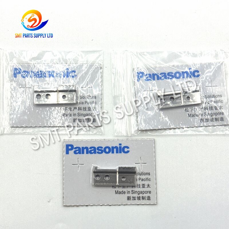
Created with Pixso. Panasonic Precision-Machined Steel Lead Cutter for RHS2B AI Machine Automatic Insertion Equipment

Panasonic Precision-Machined Steel Lead Cutter for RHS2B AI Machine Automatic Insertion Equipment

Brand Name: Panasonic
Model Number: N210133270AC
Detail Information
Place of Origin:
CHINA&JAPEN
Brand:
Panasonic
Model Number:
N210133270AC
Product Name:
Lead Cutter (A)
Alternative Description:
AI Machine Component Lead Cutter
Product Category:
Automatic Insertion Machine Spare Part
Product Type:
Steel Cutting Blade
Main Function:
Cutting Excess Electronic Component Leads
Applicable Equipment:
Automatic Insertion Equipment
Compatible Machine Reference:
RHS / RHS2 / RHS2B
Cutter Identification:
Cutter A
Related Part:
N210133271AC Cutter B
Material:
Precision-Machined Steel
Installation Position:
Lead Cutting Mechanism
Installation Method:
Mechanical Replacement
Processing Method:
Precision Machining
Operating Action:
Repeated Mechanical Shearing
Cutting Target:
Electronic Component Leads
Product Description
Panasonic N210133270AC Steel Lead Cutter A for RHS2B AI Machine

Panasonic Precision-Machined Steel Lead Cutter for RHS2B AI Machine Automatic Insertion EquipmentPanasonic Precision-Machined Steel Lead Cutter for RHS2B AI Machine Automatic Insertion EquipmentPanasonic Precision-Machined Steel Lead Cutter for RHS2B AI Machine Automatic Insertion Equipment

The Panasonic N210133270AC Lead Cutter (A) is a precision cutting component designed for compatible automatic insertion equipment, including selected RHS, RHS2, and RHS2B AI machine configurations. Installed inside the component lead processing and cutting mechanism, this cutter trims excess component leads during the automatic insertion cycle.

Stable cutting performance is important for maintaining consistent lead length, clean cutting edges, reliable PCB handling, and efficient downstream assembly. A worn, chipped, incorrectly installed, or dimensionally unsuitable cutter may cause incomplete cutting, excessive burrs, irregular lead length, component movement, or unexpected machine stoppage.

N210133270AC provides a clearly identifiable part number for maintenance teams, purchasing departments, distributors, and production engineers. It is commonly identified as Lead Cutter (A) and may operate together with the corresponding Lead Cutter (B), part number N210133271AC, depending on the machine assembly.

Before ordering, customers should compare the machine model, assembly position, old part number, cutter shape, mounting points, and machine parts list.


Product Identification
Item Description
Brand Reference Panasonic
Primary Part Number N210133270AC
Product Name Lead Cutter (A)
Product Category AI Machine Cutting Component
Component Type Machine Knife / Lead Cutting Blade
Application Automatic Component Insertion Equipment
Compatible Machine Reference RHS, RHS2, RHS2B
Main Function Cutting Excess Electronic Component Leads
Cutter Position Cutter A; commonly identified as one side of the cutting assembly
Related Cutter N210133271AC Lead Cutter (B)
Installation Type Direct Replacement According to Machine Assembly
Material Precision-Machined Steel
Order Verification Part Number, Machine Model, Position and Product Photo

Why Lead Cutting Quality Matters

Automatic insertion equipment places electronic components into prepared PCB holes at high production speed. After insertion, the component leads must be cut to a controlled length. The cutting mechanism must complete this process quickly and repeatedly without damaging the component body, PCB surface, insertion mechanism, or adjacent machine parts.

A properly selected lead cutter helps the machine maintain:

  • Consistent lead cutting length.
  • Cleaner cutting surfaces.
  • Stable automatic insertion cycles.
  • Reduced cutting resistance.
  • Lower risk of incomplete lead separation.
  • More predictable equipment maintenance.
  • Reduced production interruptions.
  • Improved spare-parts management.

Because the cutter works through repeated mechanical contact, its cutting edge can gradually wear. Regular inspection and timely replacement are important for maintaining machine performance.


Common Causes of Cutter Failure

The cutter is a wear-related mechanical component. Its operating life depends on production volume, lead material, cutter alignment, lubrication condition, machine adjustment, installation accuracy, and maintenance practices.

Common Cause Possible Result Recommended Action
Long-Term Cutting Wear Rounded cutting edge and reduced cutting efficiency Inspect the cutting edge and replace the cutter when wear exceeds the acceptable condition
Incorrect Cutter Alignment Uneven cutting, edge collision or abnormal load Recheck mounting position and cutter clearance
Hard or Oversized Component Leads Increased cutting resistance and accelerated wear Confirm component lead specifications and machine settings
Metal Dust or Lead Residue Restricted cutter movement and unstable operation Clean the cutting area according to the maintenance schedule
Incorrect Part Selection Installation difficulty or cutting-position mismatch Verify N210133270AC against the machine BOM and old part
Loose Mounting Hardware Cutter movement, vibration or irregular lead length Tighten mounting hardware to the machine maintenance standard
Damaged Mating Cutter New cutter wears rapidly or cannot cut correctly Inspect both Cutter A and Cutter B before replacement
Improper Handling Chipping or deformation before installation Use protective packaging and handle the cutting edge carefully
Insufficient Maintenance Accumulated residue and increased mechanical resistance Establish scheduled inspection and cleaning procedures
Machine Mechanism Wear Abnormal movement even after cutter replacement Inspect shafts, guides, holders and drive components

Solution

Replacing a worn cutter with the correctly identified N210133270AC Lead Cutter (A) can help restore the intended cutting action of compatible automatic insertion equipment.

For the best maintenance result, the replacement process should include more than simply removing the old cutter. Technicians should inspect the complete cutting assembly, including the mating blade, cutter holder, guide, mounting hardware, moving mechanism, cutting clearance, and surrounding components.

A complete replacement procedure generally includes:

  1. Confirming the equipment model and machine serial number.
  2. Identifying the installed cutter position.
  3. Checking the old part number and physical design.
  4. Inspecting Cutter A and Cutter B together.
  5. Cleaning lead residue from the cutting mechanism.
  6. Installing the replacement cutter in the correct direction.
  7. Adjusting alignment and cutter clearance.
  8. Performing manual or low-speed movement checks.
  9. Testing the cutter with sample components.
  10. Inspecting cut lead length and cutting-edge quality.

This systematic approach reduces the risk of repeated replacement, abnormal blade contact, or unexpected damage to the new cutter.


Key Product Features
1. Clearly Identified Part Number

The N210133270AC marking supports accurate purchasing, inventory control, maintenance records, and replacement-part verification.

2. Precision Cutting Application

The cutter is designed for repeated trimming of electronic component leads during the automatic insertion process.

3. Steel Cutting Construction

Precision-machined steel construction supports mechanical strength and repeated cutting performance under normal machine operating conditions.

4. Compatible AI Machine Application

The product is commonly supplied for selected RHS, RHS2, and RHS2B automatic insertion machine configurations. Final compatibility must be confirmed through the machine parts list.

5. Maintenance-Friendly Replacement

The cutter can be replaced as part of scheduled maintenance, machine overhaul, cutting-unit repair, or emergency spare-parts replacement.

6. Suitable for Production Spare Stock

Keeping this cutter in maintenance inventory can reduce waiting time when cutting quality decreases or unexpected blade damage occurs.

7. Pair Inspection Support

N210133270AC Cutter A can be checked together with N210133271AC Cutter B to evaluate the condition of the complete cutting pair.

8. Production Reliability Support

Correct cutter selection and installation help maintain stable component lead processing and reduce cutting-related machine alarms.


Specifications
Specification Details
Product Name Lead Cutter (A)
Main Part Number N210133270AC
Product Type Automatic Insertion Machine Cutter
Component Classification AI Machine Spare Part
Functional Category Electronic Component Lead Cutting
Machine Reference RHS / RHS2 / RHS2B
Cutting Material Electronic Component Leads
Cutter Material Precision Steel
Installation Location Lead Cutting Mechanism
Installation Method Mechanical Mounting
Operating Mode Repeated Mechanical Cutting
Related Part Number N210133271AC Lead Cutter (B)
Replacement Purpose Restore Cutting Performance
Inspection Requirement Edge Condition, Shape, Position and Mounting Points
Recommended Verification Machine Model, Serial Number, BOM and Old Part Photo
Supply Condition New, subject to quotation and stock confirmation
Packaging Individual Protective Packaging
Quantity Unit Piece
Custom Verification Available according to sample or clear product photos
Warranty Subject to quotation, condition and supply agreement

Specifications should be confirmed against the actual machine configuration before purchase. Equipment revisions may use different cutters even when the machine series name is similar.


Application

The N210133270AC Lead Cutter (A) is used in electronic manufacturing facilities operating compatible automatic insertion equipment.

Typical Application Areas
Application Area Product Function
PCB Automatic Insertion Line Cuts excess component leads after insertion
Radial Component Processing Supports controlled trimming of inserted radial leads
AI Machine Maintenance Replaces worn or damaged cutting components
Cutting Unit Overhaul Restores the mechanical cutting assembly
Electronics Production Supports continuous high-volume PCB assembly
Spare-Parts Inventory Provides emergency replacement stock
Preventive Maintenance Replaced before cutting quality affects production
Machine Refurbishment Used during repair and rebuilding of insertion equipment
Contract Electronics Manufacturing Supports maintenance of multi-shift production lines
Industrial Electronics Assembly Helps process inserted components on control boards
Typical Industries
  • Consumer electronics manufacturing.
  • Automotive electronics production.
  • Industrial control equipment assembly.
  • Power supply manufacturing.
  • Appliance control-board production.
  • Lighting electronics manufacturing.
  • Communication equipment production.
  • PCB assembly and contract manufacturing.
  • Electronic machine repair and refurbishment.
  • AI machine spare-parts distribution.

Panasonic Precision-Machined Steel Lead Cutter for RHS2B AI Machine Automatic Insertion EquipmentPanasonic Precision-Machined Steel Lead Cutter for RHS2B AI Machine Automatic Insertion EquipmentPanasonic Precision-Machined Steel Lead Cutter for RHS2B AI Machine Automatic Insertion Equipment
How It Works

The lead cutter operates as part of the automatic insertion machine’s mechanical lead-processing system.

Step 1: Component Feeding

Electronic components are supplied to the insertion head through the machine feeding system. The machine controls component orientation and insertion timing.

Step 2: Component Insertion

The insertion mechanism positions the component above the PCB and inserts its leads into the corresponding board holes.

Step 3: Lead Positioning

The component leads enter the cutting area below or within the PCB support mechanism. The cutter assembly holds the leads in the required cutting position.

Step 4: Mechanical Cutting

N210133270AC Lead Cutter (A) works with the related cutting mechanism to shear the excess lead material. Depending on the assembly design, it may operate together with Cutter B, N210133271AC.

Step 5: Cutter Return

After cutting, the moving mechanism returns to its starting position and prepares for the next insertion cycle.

Step 6: Continuous Production

The process repeats automatically for each component. Cutter sharpness, alignment, clearance, and movement directly influence the consistency of the cutting result.


Signs That the Cutter May Need Replacement

Maintenance teams should inspect the cutter when any of the following conditions occur:

Production Symptom Possible Cutter-Related Cause
Component Leads Are Not Fully Separated Cutting edge may be worn or damaged
Lead Length Becomes Inconsistent Cutter alignment or movement may be unstable
Excessive Burrs Appear Cutting edge may be rounded or chipped
Cutting Noise Increases Cutter interference or abnormal resistance may exist
Cutting Mechanism Vibrates Mounting hardware or blade alignment may be incorrect
Metal Residue Increases Cutter wear or improper clearance may be present
Machine Stops During Cutting Cutting load may exceed the normal range
New Cutter Wears Quickly Mating cutter or cutter holder may be damaged
Cutter Surface Shows Impact Marks Blade collision or incorrect installation may have occurred
Components Move During Cutting Cutting resistance or positioning may be abnormal

Not every cutting problem is caused by the cutter itself. Guides, holders, drive mechanisms, sensors, component dimensions, PCB support, and machine settings should also be inspected.


Maintenance Recommendations

Correct maintenance can help extend cutter service life and protect nearby machine parts.

Daily Inspection
  • Check the cutting area for lead fragments and metal residue.
  • Confirm that cutter movement is smooth.
  • Listen for abnormal cutting noise.
  • Check sample boards for irregular lead length.
  • Confirm that no loose components remain inside the mechanism.
Scheduled Inspection
  • Examine the cutting edge under suitable lighting.
  • Check the cutter for chips, cracks, deformation, or heavy wear.
  • Inspect the mating cutter and guide components.
  • Check mounting screws and positioning surfaces.
  • Verify cutting clearance according to machine requirements.
  • Clean the complete cutting assembly.
  • Record cutter replacement history.
Replacement Inspection

After installing N210133270AC, technicians should perform a low-speed test before returning the machine to full production. The first processed boards should be inspected for lead length, cutting completeness, component stability, and visible burrs.


How to Choose the Correct Cutter

Selecting an AI machine cutter only by visual appearance may result in an incorrect order. Similar cutters can have different angles, thicknesses, holes, mounting positions, or cutting directions.

Check the Part Number

Confirm that the existing part is marked N210133270AC or that the machine parts list specifies this number.

Confirm Cutter A or Cutter B

N210133270AC is commonly identified as Lead Cutter (A). Do not confuse it with N210133271AC Lead Cutter (B).

Verify the Machine Model

Confirm whether the machine is an RHS, RHS2, RHS2B, or another automatic insertion equipment configuration.

Check the Machine Serial Number

Machines within the same series may have different production revisions. The serial number helps identify the correct assembly version.

Compare the Old Cutter

Provide clear photographs showing:

  • The complete cutter.
  • The cutting edge.
  • Mounting holes.
  • Thickness.
  • Side profile.
  • Part number.
  • Installation position.
Check the Related Cutting Parts

Inspect whether Cutter B, the cutter holder, guides, shafts, springs, screws, or moving parts also need replacement.

Confirm Product Condition

Before ordering, specify whether the requirement is for a new branded part, verified original stock, or an alternative replacement. Product condition and source should be clearly written in the quotation.


Cutter Selection Comparison
Verification Point N210133270AC N210133271AC
Common Product Name Lead Cutter (A) Lead Cutter (B)
Component Type AI Machine Lead Cutter AI Machine Lead Cutter
Position Cutter A side Cutter B side
Can Part Numbers Be Interchanged? No No
Order Recommendation Verify old part and assembly position Verify old part and assembly position
Pair Inspection Inspect together with Cutter B Inspect together with Cutter A

The two cutter numbers should not be treated as interchangeable unless the machine documentation specifically confirms the replacement.


Quality Inspection

Before shipment, the cutter can be checked according to the agreed supply standard.

Visual Inspection
  • Product surface condition.
  • Cutting-edge condition.
  • Mounting-hole condition.
  • Part-number identification.
  • Absence of visible cracks or deformation.
  • Protective treatment and packaging.
Dimensional Confirmation

When required, dimensions can be compared with an approved sample, technical drawing, or customer-provided measurement information.

Part Number Confirmation

The quotation, packing list, package label, and product identification should use the same part number: N210133270AC.

Order Traceability

Customers are encouraged to include their purchase order number, machine reference, and required quantity so each shipment can be traced more easily.


Packaging and Shipping

The cutting edge is a precision working surface and should be protected during storage and transportation.

Standard Packaging Process
  1. Visual inspection before packing.
  2. Cutting-edge protection.
  3. Individual inner packaging.
  4. Part-number label identification.
  5. Shock-resistant outer packaging.
  6. Quantity verification before sealing.
  7. Export carton preparation.
Shipping Information Required

To prepare an accurate quotation, please provide:

  • Required quantity.
  • Destination country.
  • Preferred shipping method.
  • Machine model.
  • Machine serial number, when available.
  • Required delivery date.
  • Product condition requirement.
  • Photos of the current cutter.

International delivery options may include express courier, air freight, or consolidated shipment according to order quantity and destination.


Advantages for Maintenance Teams
Customer Requirement Product Value
Accurate Replacement Identification Clear N210133270AC part number
Reduced Machine Downtime Suitable for planned spare-parts inventory
Stable Cutting Process Supports consistent lead trimming when correctly installed
Easier Procurement Standardized product identification
Maintenance Planning Can be included in preventive replacement schedules
Complete Cutting-Unit Inspection Can be checked with N210133271AC Cutter B
Export Supply Suitable for international electronics manufacturers and service companies
Technical Confirmation Compatibility can be checked using machine and part photos

Ordering Checklist

Before submitting an inquiry, confirm the following information:

Required Information Example
Part Number N210133270AC
Product Name Lead Cutter (A)
Machine Model RHS2B
Machine Serial Number Provide if available
Required Quantity 1 piece, 2 pieces or planned stock quantity
Product Condition New or as specified
Old Part Photo Front, back, side and cutting edge
Related Part Requirement N210133271AC Cutter B
Delivery Country Customer destination
Required Delivery Time Standard or urgent
Shipping Method Courier, air freight or combined shipment

Providing complete information allows the supplier to confirm compatibility and prepare a more accurate quotation.


Frequently Asked Questions
Q1: What is the function of N210133270AC?

N210133270AC is commonly identified as Lead Cutter (A). It is installed in compatible automatic insertion equipment to cut excess electronic component leads during the insertion process. Correct installation and alignment help maintain consistent cutting length and stable machine operation.

Q2: Which machines can use this cutter?

The cutter is commonly associated with selected RHS, RHS2, and RHS2B automatic insertion machine configurations. However, equipment revisions may use different cutting components. Customers should confirm the part number through the machine BOM, old cutter marking, machine serial number, and installation photos.

Q3: Is N210133270AC interchangeable with N210133271AC?

No. N210133270AC is commonly identified as Cutter A, while N210133271AC is Cutter B. They may operate within the same cutting assembly but normally have different positions and structures. Each part number should be ordered separately according to the machine documentation.

Q4: Should Cutter A and Cutter B be replaced together?

They do not always require replacement at the same time, but both cutters should be inspected together. A damaged or heavily worn mating cutter can reduce cutting quality and may accelerate wear on the newly installed cutter. Replace both when the cutting pair is outside the acceptable condition.

Q5: What information is required before ordering?

Please provide the part number, machine model, machine serial number, required quantity, destination country, current cutter photos, installation position, and product condition requirement. Clear photos of the cutting edge and mounting holes are particularly helpful for compatibility verification.


Contact Us

SMT PARTS SUPPLY LTD supplies automatic insertion machine parts, SMT equipment components, cutters, guides, feeders, sensors, motors, control boards, and production-line maintenance parts for international electronics manufacturers.

For a fast quotation for N210133270AC Lead Cutter (A), please send:

  • Part number.
  • Product name.
  • Machine model.
  • Machine serial number.
  • Required quantity.
  • Current part photos.
  • Delivery country.
  • Required delivery schedule.

Our team can help check the part number, compare product photos, confirm related cutter requirements, and prepare suitable shipping options.

Important Trademark Notice: Panasonic and related machine names are trademarks of their respective owners. Brand names and model references on this page are used only for product identification and compatibility information. Supply condition, product source, and authenticity documentation should be confirmed in the commercial quotation.