logo
Good price  online

products details

Created with Pixso. Home Created with Pixso. Products Created with Pixso.
SMT Spare Parts
Created with Pixso. Machine-specific Conveyor X Limit Sensor for MPM125 Screen Printer with Position Confirmation

Machine-specific Conveyor X Limit Sensor for MPM125 Screen Printer with Position Confirmation

Brand Name: Speedline MPM
Model Number: 1015390-01
Detail Information
Place of Origin:
CHINA&JAPAN
Product Name:
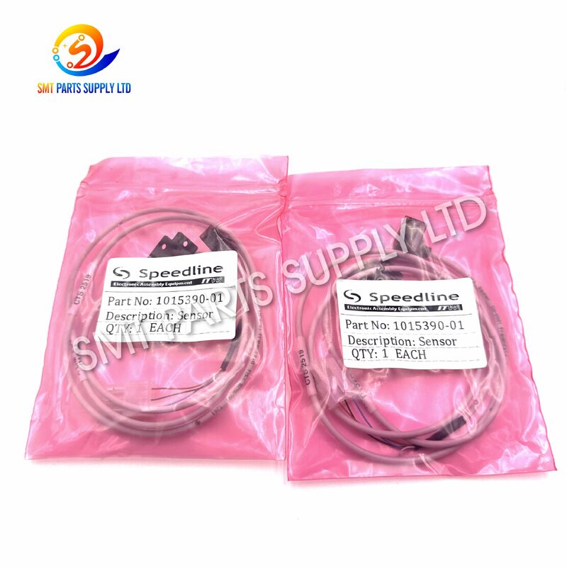
Conveyor X Limit Sensor
Reference Brand:
Speedline MPM
Part Number:
1015390-01
Related Series:
Momentum
Applicable Machine:
MPM125 Screen Printer
Product Category:
SMT Spare Parts
Equipment Category:
SMT Screen Printer
Application System:
PCB Conveyor System
Installation Position:
Conveyor X-Axis Limit Position
Secondary Function:
Position Confirmation And Homing Support
Signal Purpose:
Provides Limit Status To The Machine Controller
Component Type:
Electrical Position Sensor
Replacement Type:
Machine Maintenance Spare Part
Mounting Method:
Match The Original Machine Installation
Connector:
Machine-specific; Confirmation Required
Highlight:

MPM125 screen printer limit sensor

,

Conveyor X limit sensor with position confirmation

,

SMT spare parts for MPM125 screen printer

Product Description

Speedline MPM 1015390-01 Conveyor X Limit Sensor for MPM125 Printer

Machine-specific Conveyor X Limit Sensor for MPM125 Screen Printer with Position ConfirmationMachine-specific Conveyor X Limit Sensor for MPM125 Screen Printer with Position ConfirmationMachine-specific Conveyor X Limit Sensor for MPM125 Screen Printer with Position Confirmation

The Speedline MPM 1015390-01 conveyor X limit sensor is a machine-specific position detection component designed for the conveyor motion system of the MPM125 screen printer. Installed at the designated X-axis limit position, the sensor provides an electrical switching signal when the conveyor mechanism reaches its defined travel boundary. This signal allows the machine controller to identify the end position, stop or reverse the related motion, and maintain a controlled operating sequence.

A correctly functioning limit sensor is important for stable board transportation, reliable machine initialization, and consistent conveyor positioning. When the original sensor becomes damaged, contaminated, electrically unstable, or mechanically misaligned, the printer may display position alarms, fail to complete homing, or interrupt normal PCB transfer.

Part number 1015390-01 is supplied as a replacement spare part for maintenance and repair applications. Compatibility should be confirmed by part number, installed position, connector appearance, mounting dimensions, and machine configuration before purchase.


Why the Conveyor X Limit Sensor Is Important

The conveyor system moves printed circuit boards into, through, and out of the printing area. Its motion must remain within a controlled mechanical range. The X limit sensor acts as a position reference and travel protection component within this motion sequence.

Without a reliable limit signal, the control system may be unable to determine whether the conveyor mechanism has reached its intended boundary. This can result in repeated movement attempts, machine alarms, incomplete initialization, abnormal mechanical contact, or interrupted PCB transfer.

The sensor contributes to several important machine functions:

Function Operational Purpose
Travel limit detection Identifies when the conveyor reaches a designated boundary
Position feedback Sends a switching signal to the machine control system
Homing assistance Supports reference-position confirmation during initialization
Overtravel prevention Helps stop motion before excessive mechanical travel occurs
Process coordination Allows the conveyor sequence to continue in the correct order
Fault detection Helps the controller identify missing or abnormal position signals

Cause: Why the Original Sensor May Fail

A conveyor X limit sensor operates repeatedly whenever the machine initializes, adjusts its conveyor position, or performs the relevant motion sequence. Long-term production use can expose the component to vibration, dust, solder paste residue, cleaning chemicals, cable movement, and mechanical impact.

Sensor failure is not always caused by the sensing component alone. Wiring, connectors, mounting brackets, control inputs, and mechanical alignment should also be inspected during troubleshooting.

Common Causes of Failure
Possible Cause Description Possible Result
Normal operating wear Repeated switching cycles gradually affect sensor stability Intermittent or delayed signal
Mechanical impact Conveyor parts, tools, or incorrect adjustment may strike the sensor Cracked body or damaged sensing surface
Mounting movement Loose screws or vibration can change the sensor position Incorrect switching point
Cable fatigue Repeated cable bending may damage internal conductors Unstable signal or open circuit
Connector oxidation Moisture or contamination may affect electrical contact Intermittent alarm
Solder paste contamination Residue may collect around the sensor or target area Reduced detection reliability
Incorrect target clearance Excessive distance or poor alignment affects activation Sensor does not switch
Control input fault A problem in the input circuit can resemble sensor failure No signal detected by controller
Incorrect replacement Similar-looking sensors may have different outputs or wiring Immediate alarm or malfunction
Improper cleaning Aggressive solvents may damage plastic, seals, or cable insulation Premature component failure

Typical Machine Symptoms

A defective or incorrectly adjusted conveyor X limit sensor may produce one or more of the following symptoms:

Machine Symptom Possible Relationship to the Sensor
Conveyor X-axis limit alarm The expected switching signal is missing
Machine cannot complete initialization The controller cannot confirm the reference position
Conveyor continues moving toward the limit Sensor signal is not received or is delayed
Conveyor stops before reaching the required position Sensor is activated too early or is misaligned
Alarm appears intermittently Cable, connector, or sensor output may be unstable
PCB transfer cycle is interrupted Conveyor position is not confirmed
Alarm returns after machine restart The underlying sensor or wiring problem remains
Manual movement works but automatic mode fails Sequence logic does not receive the required position input
Sensor indicator changes but controller input does not Wiring, connector, or input module may be faulty
Controller input changes but position remains incorrect Mechanical alignment or target position may require adjustment

These symptoms can also be caused by mechanical binding, damaged cables, incorrect machine parameters, loose connectors, input board faults, or conveyor assembly problems. A complete inspection should be performed before replacing parts.


Solution: Replacement with the Correct 1015390-01 Sensor

Replacing a failed or unstable limit sensor can restore reliable conveyor position feedback and help the machine complete its normal movement sequence. The replacement part must match the original sensor in electrical characteristics, physical dimensions, mounting orientation, connector configuration, and switching behavior.

The Speedline MPM 1015390-01 conveyor X limit sensor is intended to provide a practical maintenance solution for MPM125 screen printers using the corresponding part number and conveyor configuration.

Potential Benefits of Correct Replacement
Benefit Production Value
Restored position feedback Helps the controller recognize the conveyor travel boundary
More reliable initialization Supports successful machine homing and startup
Reduced unexpected alarms Eliminates faults caused by unstable sensor signals
Improved conveyor control Maintains the intended movement and stopping sequence
Lower mechanical risk Helps prevent unnecessary travel beyond the defined limit
Faster maintenance Part-number identification simplifies replacement selection
Reduced production interruption Supports faster restoration of printer operation
More consistent PCB handling Helps maintain controlled board transport
Easier troubleshooting A stable sensor signal allows technicians to test related systems accurately

Specifications
Main Product Specifications
Specification Details
Reference Brand Speedline MPM
Part Number 1015390-01
Product Name Conveyor X Limit Sensor
Product Category SMT Screen Printer Spare Part
Primary Function Conveyor travel limit and position detection
Application Equipment MPM125 screen printer
Installation Area Conveyor X-axis limit position
Signal Function Sends a position status signal to the machine controller
Operating Role Position confirmation, homing support, and overtravel prevention
Component Type Machine-specific electrical sensing component
Mounting Method According to the original machine installation
Connector Type Must match the installed machine configuration
Cable Configuration Confirm using the original part or clear photographs
Electrical Rating Verify against the original sensor and machine documentation
Sensing Method Confirm according to the installed 1015390-01 configuration
Replacement Principle Match part number, wiring, mounting, and switching behavior
Recommended Verification Part code, connector, cable, bracket, dimensions, and machine serial number
Supply Condition Confirm with the supplier before ordering
Packing Method Protective industrial spare-parts packaging
Minimum Order Quantity Available according to current stock and quotation
Important Specification Notice

Electrical ratings, output type, connector pin assignment, cable length, sensing distance, and mounting dimensions should not be selected by appearance alone. Different sensor versions may have similar housings while using different operating voltages, output logic, wiring arrangements, or connector standards.

For accurate supply, send the following information:

  1. Full part number shown on the original component.
  2. Machine model and machine serial number.
  3. Clear front, rear, connector, cable, and label photographs.
  4. Mounting position inside the conveyor assembly.
  5. Required quantity.
  6. Existing fault message, when available.

Application

The 1015390-01 sensor is primarily used in the conveyor position-control system of the specified MPM screen printer configuration. It is suitable for maintenance departments, SMT production facilities, equipment repair companies, and spare-parts distributors requiring a replacement for the corresponding installed component.

Main Application Areas
Application Description
MPM125 screen printer maintenance Replaces a defective conveyor X limit sensor
Conveyor position repair Restores travel-boundary detection
Machine alarm troubleshooting Addresses faults related to missing limit signals
Preventive maintenance Replaces unstable sensors before complete failure
Equipment refurbishment Supports restoration of used screen-printing equipment
Spare-parts inventory Maintains critical replacement components for production lines
Emergency machine repair Reduces downtime after unexpected sensor failure
Production line relocation Replaces components damaged during transport or reinstallation
Suitable Users
  • Electronics manufacturing service providers.
  • SMT production factories.
  • PCB assembly plants.
  • Screen printer maintenance teams.
  • Industrial automation repair companies.
  • Used SMT equipment rebuilders.
  • International SMT spare-parts distributors.
  • Technical service contractors.

How It Works

The conveyor X limit sensor operates as part of the printer’s motion-control feedback system. When the conveyor mechanism moves toward its defined X-axis boundary, a mechanical target, actuator, or detectable object approaches the sensing position.

Once the required activation condition is reached, the sensor changes its electrical output state. The machine controller reads this state through the corresponding input circuit and determines that the conveyor has reached the expected limit or reference position.

The controller can then stop the related movement, reverse direction, complete a homing step, or proceed to the next stage of the operating sequence.

Basic Operating Sequence
Step Machine Action Sensor Function
1 Printer starts initialization Controller checks the current sensor state
2 Conveyor mechanism begins moving Sensor monitors the travel position
3 Target approaches the X limit position Sensor prepares to change output state
4 Target reaches the activation point Sensor sends the limit signal
5 Controller receives the input Motion is stopped, reversed, or confirmed
6 Machine completes the reference sequence Normal production operation becomes available
Signal Interpretation

A limit sensor does not directly control the conveyor motor. It provides an input signal to the machine control system. The controller interprets this signal together with software logic, motor commands, timing conditions, and other safety inputs.

For this reason, a missing conveyor limit signal may originate from several areas:

  • The sensor itself.
  • The sensor cable.
  • The connector.
  • The wiring harness.
  • The controller input terminal.
  • The input board.
  • The mechanical target.
  • The mounting bracket.
  • The machine parameter or control sequence.

Machine-specific Conveyor X Limit Sensor for MPM125 Screen Printer with Position ConfirmationMachine-specific Conveyor X Limit Sensor for MPM125 Screen Printer with Position ConfirmationMachine-specific Conveyor X Limit Sensor for MPM125 Screen Printer with Position Confirmation
How to Choose the Correct Sensor

Correct selection requires more than matching the general product appearance. Industrial sensors may look identical while using different wiring, output polarity, connector pin assignments, sensing ranges, or mounting arrangements.

Selection Checklist
Verification Item What to Check Importance
Part number Confirm 1015390-01 on the original part or machine parts list Essential
Machine model Confirm the printer is the specified MPM125 configuration Essential
Machine serial number Identify production version and installed configuration Highly recommended
Connector Compare shape, number of pins, keying, and locking method Essential
Cable Compare length, exit direction, protection sleeve, and routing Important
Mounting holes Confirm spacing, orientation, and bracket arrangement Essential
Sensor body Compare dimensions and sensing-face position Important
Output behavior Confirm switching logic and electrical compatibility Essential
Installation location Confirm the sensor is used at the conveyor X limit position Essential
Existing label Send a clear photograph of all readable markings Highly recommended
Recommended Ordering Method

For the fastest quotation and lowest selection risk, provide:

Part Number + Machine Model + Serial Number + Original Part Photos + Quantity + Delivery Country

Example inquiry format:

Part required: Speedline MPM 1015390-01
Machine model: MPM125
Application: Conveyor X limit position
Quantity: 2 pieces
Machine serial number: Available upon request
Photos: Front, label, connector, cable, and mounting position attached


Difference Between a Limit Sensor Fault and a Mechanical Conveyor Fault

Before replacement, technicians should distinguish an electrical sensing problem from a mechanical motion problem.

Inspection Result More Likely Cause
Conveyor cannot move manually Mechanical binding, motor, driver, or transmission issue
Conveyor moves but no sensor state change occurs Sensor, target, wiring, or alignment problem
Sensor indicator changes but controller input remains unchanged Cable, connector, or input circuit problem
Controller input changes correctly but alarm remains Sequence logic, timing, or another interlock
Sensor activates too early Incorrect mounting or target adjustment
Sensor activates only when pressed or moved Loose mounting or internal sensor damage
Alarm occurs only during vibration Intermittent cable or connector contact
Alarm disappears after cable movement Broken conductor or poor connector connection
Replacement sensor fails immediately Incorrect electrical specification or wiring
Conveyor travels beyond the expected limit Missing sensor input, incorrect mounting, or control fault

Installation Guidance

Installation should be completed by trained maintenance personnel familiar with SMT screen printers and industrial electrical systems.

Recommended Installation Procedure
  1. Stop the machine and follow the facility’s electrical isolation procedure.
  2. Record the existing sensor position before removal.
  3. Photograph the cable routing, connector orientation, bracket position, and target clearance.
  4. Check the replacement part number and physical configuration.
  5. Disconnect the original sensor without pulling directly on the cable.
  6. Remove the mounting screws and retain any spacers or brackets.
  7. Install the replacement sensor in the same orientation.
  8. Route the cable away from moving parts, sharp edges, and high-temperature areas.
  9. Connect the plug securely and confirm that the locking mechanism is engaged.
  10. Restore power according to approved maintenance procedures.
  11. Check the sensor state in the machine input or diagnostic screen.
  12. Move the conveyor slowly in manual mode.
  13. Confirm that the signal changes at the correct position.
  14. Verify that the conveyor stops before reaching a damaging mechanical limit.
  15. Complete machine initialization and perform several empty-board transfer cycles.
  16. Recheck mounting screws and cable routing after the test.
Installation Precautions
  • Do not modify the connector without confirming the pin assignment.
  • Do not install a sensor based only on housing appearance.
  • Do not pull or sharply bend the cable.
  • Do not allow the moving target to strike the sensor body.
  • Do not use excessive tightening force on plastic mounting areas.
  • Do not change the activation position without recording the original setting.
  • Do not bypass the limit signal for normal production.
  • Do not apply an unverified voltage to the sensor.
  • Do not use aggressive solvents on the sensor housing or cable.
  • Do not begin automatic operation until manual verification is complete.

Testing and Troubleshooting
Pre-Replacement Checks

Before replacing the sensor, inspect the following:

Check Recommended Action
Sensor surface Remove dust and residue using an approved cleaning method
Mounting screws Tighten loose hardware carefully
Target alignment Confirm the moving target reaches the sensing area
Connector condition Inspect for bent pins, oxidation, looseness, or contamination
Cable condition Look for cuts, compression, hard bends, or broken insulation
Input status Check whether the machine diagnostic screen changes
Power supply Verify the correct supply according to machine documentation
Mechanical movement Confirm the conveyor reaches the expected position freely
Alarm history Record the exact alarm code and operating condition
Replacement history Check whether an incorrect part was installed previously
Post-Replacement Checks

After installation, verify:

  • The sensor is mounted securely.
  • The target approaches the correct sensing area.
  • The input state changes consistently.
  • The signal is stable during cable movement.
  • The conveyor stops at the intended location.
  • The printer completes initialization normally.
  • PCB transfer proceeds without abnormal interruption.
  • No new sensor, conveyor, or safety alarm appears.
  • The cable remains clear of all moving components.
  • The machine performs multiple cycles consistently.

Preventive Maintenance Recommendations

Regular inspection can identify sensor problems before they cause complete machine stoppage.

Maintenance Item Recommended Practice
Visual inspection Check the sensor during scheduled conveyor maintenance
Cleaning Remove dust and residue using approved materials
Mounting check Confirm that screws and brackets remain secure
Cable inspection Check for wear, compression, and repeated bending
Connector inspection Confirm full engagement and clean contact surfaces
Target clearance Verify that the activation position has not shifted
Signal test Observe input status during manual conveyor movement
Spare inventory Keep at least one verified part for critical equipment
Maintenance records Record replacement date, alarm history, and machine serial number
Technician training Ensure staff understand signal testing and alignment procedures

The appropriate inspection interval depends on machine utilization, factory conditions, maintenance standards, and previous failure history.


Product Advantages
Accurate Part-Number Identification

The 1015390-01 reference allows maintenance teams to search for a defined machine spare part rather than selecting a general-purpose sensor without sufficient compatibility information.

Designed for Conveyor Position Detection

The component is used to detect the designated conveyor X-axis travel limit and provide the required position status to the machine control system.

Supports Stable Machine Initialization

A reliable sensor signal helps the printer confirm its reference position during startup and recover from conveyor-related alarms.

Reduces Troubleshooting Time

Replacing a confirmed defective sensor can eliminate repeated testing of an unstable component and allow technicians to continue checking the wider conveyor system.

Suitable for Preventive Spare Inventory

Production facilities operating MPM equipment can keep verified critical sensors in stock to shorten emergency repair time.

International Spare-Parts Support

The product can be quoted for electronics factories, equipment service companies, and SMT spare-parts distributors requiring international shipment.


Quality Inspection

Each supplied component should be checked according to the order requirements and available testing conditions.

Recommended Inspection Points
Inspection Category Inspection Content
Identification Confirm product name and part number
Appearance Check housing, cable, connector, and mounting points
Connector Check pin condition and locking structure
Cable Inspect insulation, strain relief, and cable exit
Dimensions Compare critical mounting dimensions when required
Electrical check Test continuity or output behavior when applicable
Packing Protect the sensor body and connector during shipment
Order verification Match quantity and customer-provided reference information

Because machine versions may differ, final compatibility remains dependent on the customer’s installed configuration.


Packaging and Shipping

The sensor should be packed to protect the sensing body, cable, and connector from impact, compression, moisture, and electrostatic exposure during transportation.

Typical Packing Process
  1. Visual inspection before packing.
  2. Protective wrapping around the sensor body.
  3. Cable arranged without tight bending.
  4. Connector protected against impact and contamination.
  5. Individual inner packaging.
  6. Part-number identification label.
  7. Reinforced outer carton for international transportation.
  8. Additional protection according to shipment quantity and destination.

Available shipping methods may include international express, air cargo, consolidated shipment, or shipment together with other SMT spare parts.


Information Required for Quotation

To receive an accurate quotation, send the following details:

Required Information Example
Product name Conveyor X Limit Sensor
Part number 1015390-01
Equipment Speedline MPM screen printer
Machine model MPM125
Required quantity 1, 2, 5, or more pieces
Original part photos Label, body, connector, and cable
Machine serial number Recommended for compatibility checking
Delivery country Required for freight estimation
Required delivery time Standard or urgent
Additional parts Provide a complete spare-parts list when available

FAQ
1. What is the function of the Speedline MPM 1015390-01 sensor?

The 1015390-01 sensor detects the designated conveyor X-axis travel limit and sends a position signal to the printer control system. This signal supports conveyor stopping, reference-position confirmation, machine initialization, and normal PCB transfer sequencing.

2. Is 1015390-01 suitable for every Speedline MPM screen printer?

No. Compatibility should not be assumed for every MPM printer. The part is listed for the specified MPM125 conveyor application, but the machine serial number, connector, cable, mounting arrangement, and installed part number should be checked before ordering.

3. How can I confirm whether the sensor is defective?

Check the sensor indicator or machine input status while moving the conveyor manually. Also inspect the target alignment, connector, cable, supply, and controller input. A sensor may operate correctly while a broken cable or faulty input circuit prevents the controller from receiving its signal.

4. What information should I provide before purchasing?

Provide part number 1015390-01, machine model, serial number, required quantity, delivery country, and clear photographs of the original sensor. Connector, cable, label, mounting holes, and installation position should be visible in the photographs.

5. Can a similar-looking general-purpose sensor replace this part?

A similar appearance does not confirm compatibility. The replacement must match the required voltage, output behavior, connector pin assignment, cable arrangement, sensing characteristics, mounting dimensions, and activation position. An incorrect sensor can cause alarms, wiring damage, or unreliable conveyor operation.


Contact Us

SMT PARTS SUPPLY LTD. supplies screen printer parts, SMT machine spare parts, sensors, motors, control boards, conveyor components, feeders, nozzles, and maintenance items for electronics manufacturing equipment.

For a fast quotation, please send:

  • Part number: 1015390-01
  • Machine model: MPM125
  • Original component photographs
  • Machine serial number
  • Required quantity
  • Delivery country
  • Expected delivery date
  • Other spare parts required for the same machine

Our sales team will check the product reference, availability, packing requirements, and shipping options according to your inquiry.

Contact us today for pricing, compatibility checking, delivery information, and combined SMT spare-parts quotations.